SiC MOSFET gate pole auxiliary circuit based on bridge circuit

A bridge circuit and auxiliary circuit technology, applied in the field of power electronics, can solve the problems of reducing device breaking speed, series disturbance, complex control, etc., and achieve the effects of convenient negative pressure, safety assurance, and simple principle

Inactive Publication Date: 2020-09-01
NANJING INST OF TECH
View PDF16 Cites 2 Cited by
  • Summary
  • Abstract
  • Description
  • Claims
  • Application Information

AI Technical Summary

Problems solved by technology

However, as the switching speed of devices continues to increase, parasitic parameters that were previously ignored in bridge circuits have become the primary factor that threatens the application of SiC MOSFET circuits.
Parasitic capacitors are prone to series disturbances in high-frequency applications of the bridge arm topology. Series disturbances cause positive voltage spikes to cause false conduction of the device, and negative voltage spikes can cause device damage. Therefore, the traditional gate drive circuit can no longer meet the requirements of SiC MOSFETs at high frequencies. The reliability needs to be improved
[0003] At present, in terms of suppressing series disturbance, according to different principles, it can be roughly divided into two types: gate impedance control and gate voltage control. The most typical method in gate impedance control is to connect an auxiliary capacitor in parallel, but the access of the auxiliary capacitor It will reduce the breaking speed of the device and increase the breaking loss. The easiest way to control the gate voltage is to add a negative voltage source, which takes advantage of the negative voltage resistance of SiC MOSFET devices
Many schemes can achieve crosstalk suppression, but they all have disadvantages such as reduced breaking speed and complicated control.

Method used


Image

  • SiC MOSFET gate pole auxiliary circuit based on bridge circuit
  • SiC MOSFET gate pole auxiliary circuit based on bridge circuit
  • SiC MOSFET gate pole auxiliary circuit based on bridge circuit

Examples


Embodiment Construction

[0028] The present invention will be further described below in conjunction with the accompanying drawings.

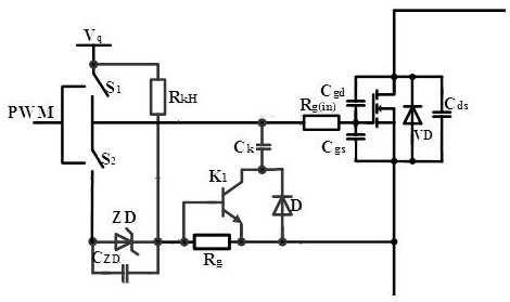
[0029] Such as figure 1 As shown, the present invention discloses a SiC MOSFET gate auxiliary circuit based on a bridge circuit, including a drive circuit, a negative voltage generation module and a crosstalk suppression module; wherein, a drive circuit is provided between the gate and the source of the SiC MOSFET , the negative pressure generating module is connected in series with the drive circuit, and the crosstalk suppression module is connected in parallel with the drive circuit.

[0030] The drive circuit includes the power module V q , the pulse module PWM, the first switching tube S 1 , the second switch tube S 2 , drive resistance R g and drive internal resistance R g(in) , where the first switching tube S 1 and the second switch tube S 2 It is a push-pull switch tube, controlled by the pulse module PWM and connected with the power module V q series, ...


PUM


Abstract

The invention discloses a SiC MOSFET gate pole auxiliary circuit based on a bridge circuit. The SiC MOSFET gate pole auxiliary circuit comprises a driving loop, a negative voltage generation module and a crosstalk suppression module. The driving loop comprises a driving resistor, the negative voltage generation module is formed by connecting a capacitor and a Zener diode in parallel and then connecting the capacitor and the Zener diode with the power supply module in series, the crosstalk suppression module comprises a triode and a diode which are in anti-parallel connection and then is connected with a suppression capacitor, and a triode base is connected with an emitter and the driving resistor in parallel; a driving loop is arranged between the grid electrode and the source electrode ofeach SiC MOSFET, the negative voltage generation module is connected with the driving loop in series, and the crosstalk suppression module is connected with the driving loop in parallel. The circuitis composed of passive devices, and the structure is simple; a driving negative voltage power supply does not need to be additionally arranged, the driving negative voltage can be adjusted by a Zenerdiode, and various driving requirements can be met; and the problem of voltage spikes when series disturbance occurs is effectively solved, and device safety is ensured.

Description

technical field [0001] The invention belongs to the field of power electronics, and in particular relates to a bridge circuit-based SiC MOSFET gate auxiliary circuit. Background technique [0002] As a new type of power electronic device, SiC MOSFET has many advantages of SiC material, making it an ideal choice for high-frequency and high-voltage circuits. However, as the switching speed of devices continues to increase, the parasitic parameters that were previously ignored in bridge circuits have become the primary factor that threatens the application of SiC MOSFET circuits. Parasitic capacitors are prone to series disturbances in high-frequency applications of the bridge arm topology. Series disturbances cause positive voltage spikes to cause false conduction of the device, and negative voltage spikes can cause device damage. Therefore, the traditional gate drive circuit can no longer meet the requirements of SiC MOSFETs at high frequencies. reliability needs to be impro...

Claims


Application Information

Patent Timeline
IPC IPC(8): H02M1/08H02M1/088H02M1/32
CPCH02M1/08H02M1/088H02M1/32H02M1/0038Y02B70/10
Inventor 李珅张宇李先允
Owner NANJING INST OF TECH
Why Eureka
Try Eureka