Minimal quantity lubrication cutter and lubrication method thereof

A kind of micro-lubrication and tool technology, which is applied in the direction of tools for lathes, manufacturing tools, accessories of tool holders, etc. It can solve the problems of inaccurate cooling points, unsatisfactory lubrication and cooling effects, etc., and achieve easy operation. Effect

Pending Publication Date: 2020-09-04
CHENGDU TOOL RES INST
View PDF11 Cites 4 Cited by
  • Summary
  • Abstract
  • Description
  • Claims
  • Application Information

AI Technical Summary

Problems solved by technology

[0008] The present invention intends to provide a minimal lubrication tool to solve the problem that the cooling position is not accurate, and the lubrication and cooling effect cannot reach the ideal state due to the change of the cutting system during the machining process.

Method used


Image

  • Minimal quantity lubrication cutter and lubrication method thereof
  • Minimal quantity lubrication cutter and lubrication method thereof
  • Minimal quantity lubrication cutter and lubrication method thereof

Examples


Embodiment 1

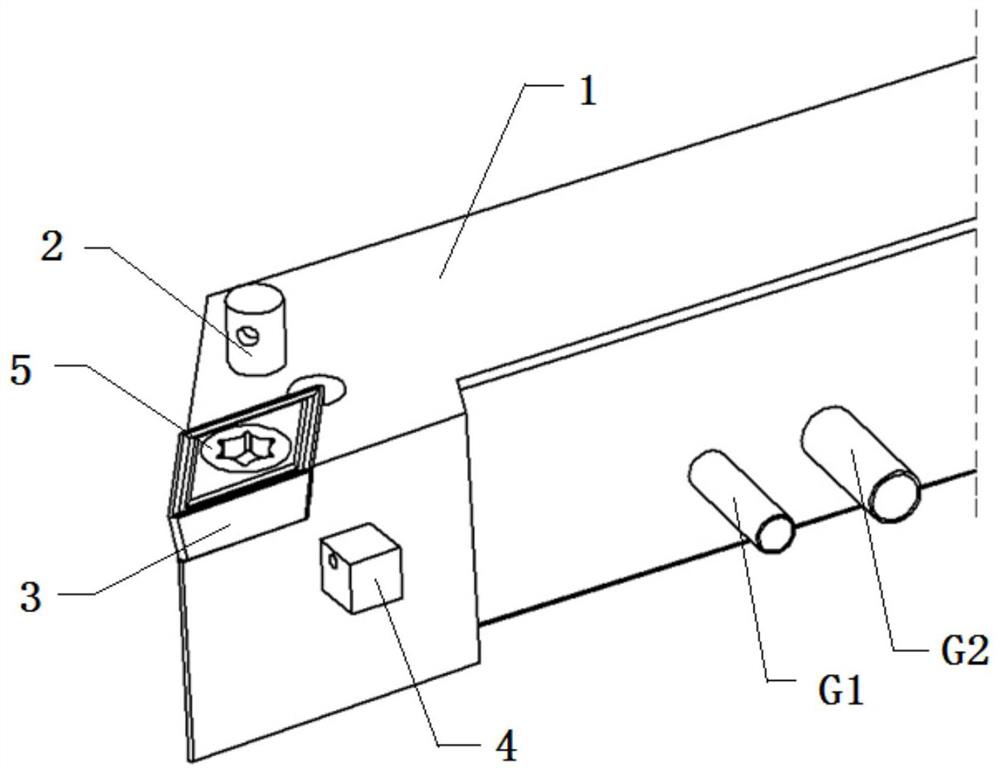
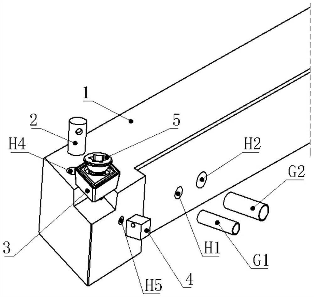
[0043] The embodiment is basically as attached figure 1 And attached figure 2 Shown: the minimal quantity lubrication tool in this embodiment is suitable for minimum quantity lubrication and cooling cutting process. Solve the problem that the cooling position is not accurate in the minimal quantity lubrication and cooling cutting process, and the lubrication and cooling effect cannot reach the ideal state due to the change of the cutting system during the machining process.

[0044] Minimal quantity lubrication tool consists of the following parts:

[0045] The first pipeline G1 used to connect the micro-lubrication medium generator with the cutter body; its main function is to transport the medium generated by the micro-lubrication medium generator to the inside of the cutter body.

[0046] Used to connect the compressed high-pressure air to the second pipe G2 of the cutter body; its main function is to deliver the high-pressure gas to the inside of the cutter body.

[00...

Embodiment 2

[0063] The difference from Embodiment 1 is that in this embodiment, an electrostatic device is installed in the mixing channel, which can charge the MQL mixture with static electricity when it is formed, and can increase its adhesion to the blade.

Embodiment 3

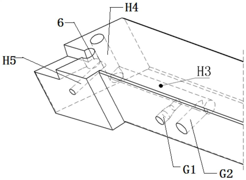
[0065] The difference from Embodiment 1 is that the axial structure of the mixing channel in this embodiment is a tapered pipe structure whose two ends are connected in two directions and the longitudinal section gradually increases toward the two ends. Through such a structure, the high-pressure air and the micro-lubrication medium can be quickly accommodated into the mixing channel, and the two are quickly compressed due to the shape of the mixing channel, so that the micro-lubrication mixed gas is compressed and atomized to form a fine uniform liquid Drops of granules for better spraying onto the blades for lubrication and cooling.


PUM


Abstract

The invention relates to the technical field of minimum quantity lubrication, and discloses a minimum quantity lubrication cutter. The cutter comprises a cutter body, wherein a mixing channel used forintroducing a minimum quantity lubrication medium and high-pressure air and mixing and vaporizing the minimum quantity lubrication medium and the high-pressure air to form minimum quantity lubrication mixed gas, a first pipeline used for allowing the minimum quantity lubrication medium to enter, a second pipeline used for allowing high-pressure air to enter, and an outflow channel used for allowing the minimum quantity lubrication mixed gas to flow out are arranged in the cutter body, the first pipeline and the second pipeline communicate with the mixing channel, the outflow channel communicates with the mixing channel, a blade for cutting is arranged on the cutter body, the outflow channel comprises a fourth channel and a fifth channel which are located on the two sides of the blade, a first guide column for connecting and guiding the fourth channel is arranged on the cutter body, and a second guide column for connecting and guiding the fifth channel is arranged on the cutter body. The invention further discloses a lubrication method of the minimum quantity lubrication cutter. The problem that a cooling site is inaccurate is effectively solved.

Description

technical field [0001] The invention relates to the technical field of micro-lubrication, in particular to a micro-lubrication tool and a lubrication method thereof. Background technique [0002] In the cutting process, in order to reduce the cutting temperature, prolong the tool life and improve the surface quality and dimensional accuracy of the workpiece, cutting fluid is widely used. In traditional machining, cutting fluid is generally supplied by pouring to lubricate and cool the machining area. [0003] While cutting fluid brings benefits to the machinery manufacturing industry, it also produces unfavorable factors such as resource consumption, environmental pollution and affecting the health of employees. Dry cutting without cutting fluid is currently only suitable for high-speed cutting of cast iron and ordinary steel, and is not suitable for high-temperature alloys and titanium alloys. Dry machining is an ultimate development direction of mechanical manufacturing ...

Claims


Application Information

Patent Timeline
Patent Type & Authority Applications(China)
IPC IPC(8): B23B27/10B23Q11/10
CPCB23B27/10B23Q11/1046Y02P70/10
Inventor 李代刚陈云刘念聪张文曾莉
Owner CHENGDU TOOL RES INST
Why Eureka
Try Eureka