
Universal on-machine non-contact calibration method for eccentric parameters of milling cutter

A calibration method and non-contact technology, applied in metal processing mechanical parts, measuring/indicating equipment, metal processing equipment, etc., can solve the limitations of unfavorable high-precision CNC milling, quantitative evaluation of difficult tool eccentricity, analysis methods and means And other issues

Active Publication Date: 2020-09-04
XI AN JIAOTONG UNIV
View PDF11 Cites 8 Cited by
  • Summary
  • Abstract
  • Description
  • Claims
  • Application Information

AI Technical Summary

Problems solved by technology

These two methods use the milling force experimental test data to indirectly identify the tool eccentricity parameters, which cannot eliminate the impact of the vibration of the cutting link, and most of them only consider the offset in the geometric axis deflection of the tool side edge , the deviation of the geometrical axis of the side edge of the tool, the deviation of the rotation axis of the side edge of the tool, the eccentricity of the end edge of the tool, etc. are not considered too much
[0005] To sum up, the existing analysis methods and means for tool eccentricity factors are very limited, and it is difficult to conduct convenient and quantitative evaluation of tool eccentric state, which is not conducive to the realization of high-precision CNC milling.

Method used


Image

  • Universal on-machine non-contact calibration method for eccentric parameters of milling cutter
  • Universal on-machine non-contact calibration method for eccentric parameters of milling cutter
  • Universal on-machine non-contact calibration method for eccentric parameters of milling cutter

Examples


Embodiment Construction

[0149] The present invention will be described in detail below with reference to the drawings and embodiments.

[0150] A universal on-machine non-contact calibration method for milling cutter eccentricity parameters, including the following steps:

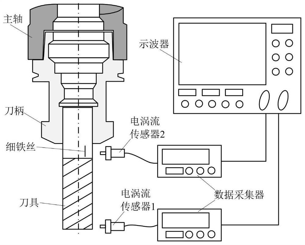
[0151] Step 1) Reference figure 1 , Build a non-contact measurement system for milling cutter eccentricity parameters on the machine, and make preparations before calibration and testing;

[0152] 1.1) Tool installation:

[0153] Prepare the tool that needs to be calibrated with eccentric parameters, and prepare a thin iron wire (diameter ≤0.05mm, length about 5mm), use tape to wrap the thin iron wire on the tool shank; connect the tool to the handle, and attach the handle Installed on the spindle of the machine tool to ensure that the spindle can operate normally;

[0154] 1.2) Measuring instrument installation:

[0155] Prepare an eddy current non-contact measurement system, including eddy current sensors, data collectors and oscilloscop...


PUM


Abstract

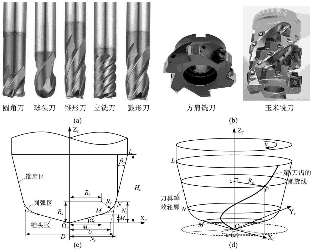
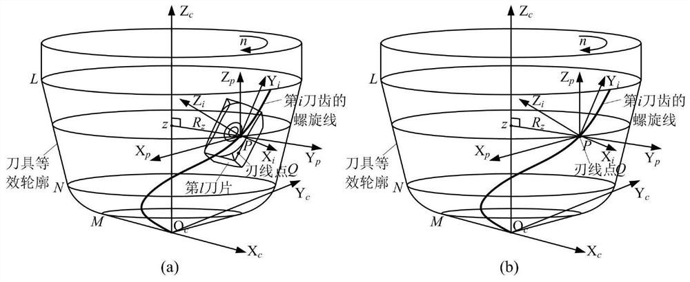
The invention relates to a universal on-machine non-contact calibration method for eccentric parameters of a milling cutter. The method comprises the following steps of establishing a universal geometrical parameter representing mathematic model of an integral milling cutter and a machine clamped milling cutter; then carrying out quantitative description on the eccentric state of a tool by means of three states such as spin axis deflection, geometrical axis deflection and end edge eccentricity of the tool and seven independent parameters; and carrying out non-contact measurement on a target distance of a cutter tooth segment of the tool mounted on a spindle of a machine tool by using an electrical vortex sensor to obtain variable quantities of actual cutting diameters of cutting points ofdifferent blades on different cutter teeth of the tool at different axial heights so as to calibrate the eccentric parameters (including geometrical axis deflection of side edge, spin axis deflectionof the side edge and end edge eccentricity of the tool) of the tool in a rotating state of the spindle by combining a numerical optimization method. The method is better in universality and accuracy,can calibrate the eccentric state of the tool quickly and accurately on-machine, and is convenient to use in an enterprise machining site.

Description

Technical field [0001] The invention belongs to the technical field of high-precision numerical control milling processing, and particularly relates to a universal on-machine non-contact calibration method for milling cutter eccentricity parameters. Background technique [0002] Tool eccentricity, as a disturbing factor in the milling process, has become one of the main unfavorable factors affecting machining efficiency and quality. Tool eccentricity is very common in the machining process of machine tools. The main reason for its occurrence is the non-ideal installation state of the spindle-toolholder-tool, the geometric error of the spindle system axis, the manufacturing error of the tool itself, and the cutting process caused the cutting edge wear. , The flexible vibration characteristics of the spindle system during operation and other factors. At present, with the continuous improvement of processing quality and efficiency requirements, the phenomenon of tool eccentricity a...

Claims


Application Information

Patent Timeline
IPC IPC(8): B23Q17/09
CPCB23Q17/09
Inventor 张星潘天航赵万华赵钊尹佳
Owner XI AN JIAOTONG UNIV
Learn More