
Low-melting-point optical glass forming device

An optical glass and molding device technology, applied in glass molding, glass pressing, glass manufacturing equipment, etc., can solve problems such as difficulty in producing low-melting glass, poor viscosity of glass liquid, easy generation of convective streaks, etc. Path and residence time, narrowing temperature and viscosity differences, the effect of preventing convection streaks

Active Publication Date: 2020-09-04
HUBEI NEW HUAGUANG NEW INFORMATION MATERIALS CO LTD
View PDF11 Cites 3 Cited by
  • Summary
  • Abstract
  • Description
  • Claims
  • Application Information

AI Technical Summary

Problems solved by technology

[0006] Both of the above two patents provide to reduce the surface temperature of the glass sheet to prevent the generation of volatile streaks, but they have limited effect on reducing the temperature of the glass liquid in the middle of the sheet and increasing the viscosity , as the thickness of the sheet increases, this surface cooling method is less effective in increasing the viscosity of the glass liquid in the middle of the sheet. When the thickness of the sheet exceeds 10mm, it has little effect on solving the convection streaks caused by the difference in viscosity between the inside and outside of ordinary glass.
Especially for low-melting glass, due to its long material properties, it is difficult to shape the sheet in the mold during the molding process, and it is easy to produce convection streaks, which will intensify as the thickness of the specification increases. The molding equipment and methods described in these two patents are difficult to solve. The problem of convection stripes in the middle of low melting point glass brings difficulties to production, so it is urgent to develop a mold and molding method to solve the above problems

Method used


Image

  • Low-melting-point optical glass forming device
  • Low-melting-point optical glass forming device
  • Low-melting-point optical glass forming device

Examples


Embodiment Construction

[0041] The present invention will be further described below in conjunction with the accompanying drawings.

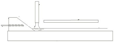
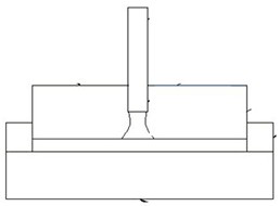
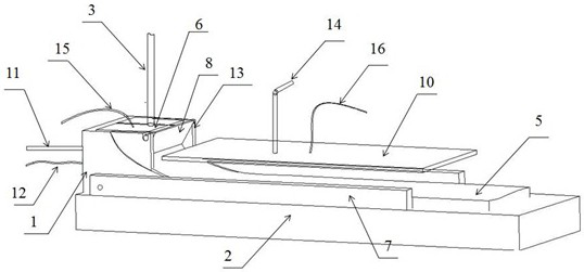
[0042] Such as Figure 3-5shown. The low-melting point optical glass molding device of the present invention comprises a mold rear baffle 1, a mold bottom plate 2, a glass leakage pipe 3, a mold space cover 10, a mold side baffle 7, a material retaining plate 8, a rear baffle cover 6, a rear Baffle temperature monitoring thermocouple 12 and baffle plate fixing frame 13. Wherein, the mold back baffle 1 forms a U-shaped groove with the mold side baffle 7 and the mold bottom plate 2, and the working surface of the mold back baffle 1 contacting the glass liquid is an arc surface. The working surface of the mold back baffle is designed to be arc-shaped in the direction of glass running, so that the molten glass can flow directly to the mold back baffle. At the same time, the arc shape of the working surface also prolongs the path for the glass liquid to enter the forming ...


PUM

PropertyMeasurementUnit
crystallization temperatureaaaaaaaaaa

Abstract

The invention provides a low-melting-point optical glass forming device, and belongs to the technical field of optical glass forming. The problem that stripes are formed on the surface of a low-melting-point optical glass strip is mainly solved. According to the main scheme, the device is characterized in that a striker plate and a striker plate fixing frame are additionally arranged on a mold rear baffle; a leaking groove with a triangular section is formed by the striker plate and the mold rear baffle; under the action of the leaking groove, molten glass flowing out of a material pipe is changed into a strip shape from a columnar shape, the superficial area of the molten glass is increased, the cooling efficiency of a mold on the molten glass is improved, meanwhile, the temperature difference between the center and the edge of the molten glass is reduced, the viscosity difference is reduced, and convection stripes caused by large viscosity difference between the center and the edge during columnar molten glass forming can be prevented; and meanwhile, the arc-shaped structure of the working surface of the rear baffle is formed, so that the molten glass directly flows onto the rearbaffle to be cooled, the stroke and retention time of the molten glass on the mold are prolonged, the molten glass is cooled in a shaping area range on the rear baffle, and convection stripes causedby high molding temperature and low viscosity are prevented.

Description

technical field [0001] The invention belongs to the technical field of optical glass molding, and relates to a molding device for low melting point optical glass strips. Background technique [0002] With the continuous development of digital cameras, digital video cameras and camera phones to better image quality and higher definition, aspheric lenses are used more and more widely. For this reason, glass with high refractive index, low dispersion and high transmittance It is more and more favored by the market. At the same time, in order to reduce processing difficulty and production cost, precision molding technology has become the first choice for optical glass to manufacture optical lenses. However, if the obtained optical glass is suitable for precision molding, it must have a lower transition temperature, which also affects optical Glass developers put forward higher requirements. [0003] Most of this kind of optical glass with low melting point contains rare earth ...

Claims


Application Information

Patent Timeline
Patent Type & Authority Applications(China)
IPC IPC(8): C03B11/08C03B11/12
CPCC03B11/08C03B11/125Y02P40/57
Inventor 胡弦寇小勇翟军周希光王亮
Owner HUBEI NEW HUAGUANG NEW INFORMATION MATERIALS CO LTD
Learn More