Hydraulic-mechanical combined rock-breaking milling wheel and double-wheel slot milling machine

A hydraulic machinery and double-wheel milling technology, which is applied to mechanically driven excavators/dredgers, earth movers/shovels, construction, etc., can solve the problem of inability to deal with rocks in the blind area of ​​milling, loss of milling tooth life, and slot milling machine Reduced work efficiency and other problems, to achieve the effect of reducing rock breaking energy consumption, reducing wear of milling teeth, and reducing construction costs

Pending Publication Date: 2020-09-04
INST OF ROCK AND SOIL MECHANICS - CHINESE ACAD OF SCI
View PDF0 Cites 2 Cited by
  • Summary
  • Abstract
  • Description
  • Claims
  • Application Information

AI Technical Summary

Problems solved by technology

[0006] This application provides hydraulic machinery combined with rock-breaking milling wheel and double-wheel milling machine, which solves the problem that in the prior art, when encountering hard rock formations, the working efficiency of the milling machine decreases and the service life of the milling teeth is seriously lost, and the technology that cannot deal with rocks in the blind area of ​​milling The problem is that the rock-breaking efficiency and rock-breaking effect have been improved compared with the traditional mechanical rock-breaking method, the wear of the tool is small, and it has a better milling effect on the milling blind area, which is conducive to improving construction efficiency and reducing construction costs. technical effect

Method used


Image

  • Hydraulic-mechanical combined rock-breaking milling wheel and double-wheel slot milling machine
  • Hydraulic-mechanical combined rock-breaking milling wheel and double-wheel slot milling machine
  • Hydraulic-mechanical combined rock-breaking milling wheel and double-wheel slot milling machine

Examples


Embodiment Construction

[0064] In order to make the purpose, technical solution and advantages of the present application clearer, the implementation manners of the present application will be further described in detail below in conjunction with the accompanying drawings.

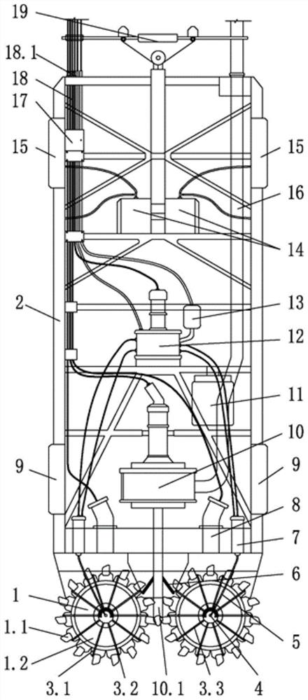
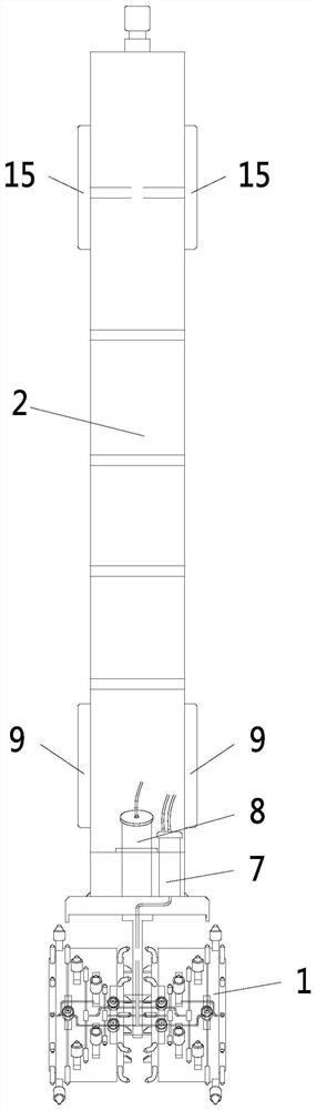
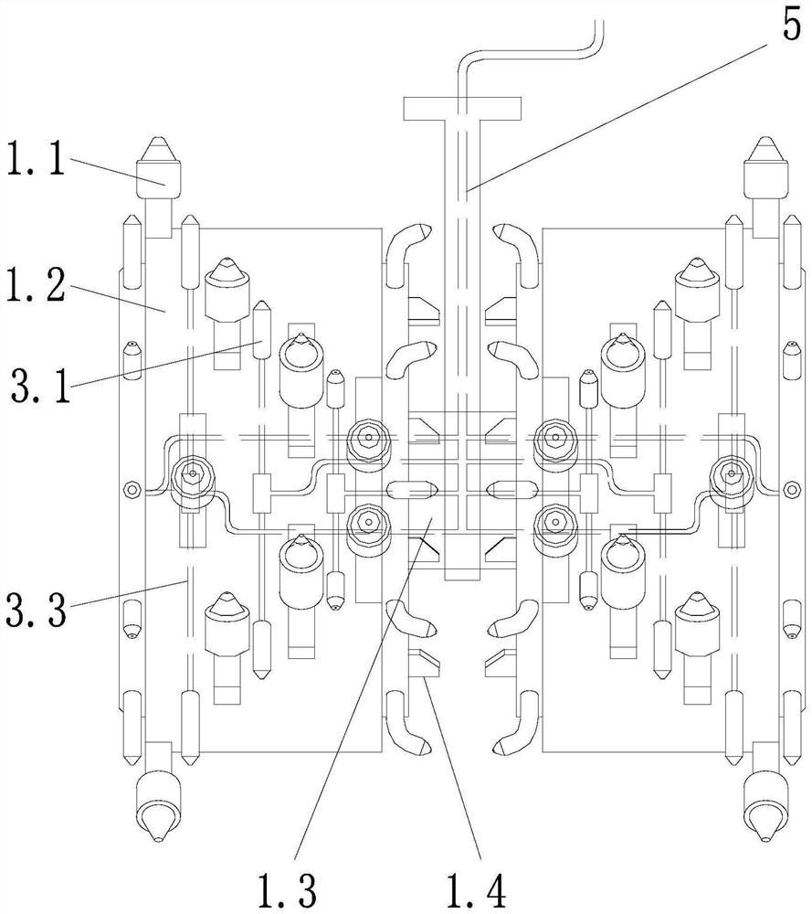
[0065] See attached Figure 1-8 , The hydromechanical combined rock-breaking milling wheel 1 of the present application includes a milling wheel main body 1.2, a plurality of milling teeth 1.1, a plurality of picks 1.4, a milling wheel spindle 1.3 and a high-pressure water jet device 3.

[0066] See attached Figure 3-5 , the milling teeth 1.1 are arranged on the milling wheel main body 1.2; the milling teeth 1.1 are arranged at intervals, and the shape formed by connecting the center points of each milling tooth 1.1 is the function image shape of the sine function y=sinωx, wherein the value of ω is measured according to the test , or take the engineering experience value, where the value of ω is measured according to the test, ...


PUM


Abstract

The invention relates to a hydraulic-mechanical combined rock-breaking milling wheel and a double-wheel slot milling machine. The milling wheel comprises a milling wheel body, multiple milling teeth,multiple cutting teeth, a milling wheel spindle and a high-pressure water jet device, wherein the multiple milling teeth are fixed to the circumference of the milling wheel body; the multiple cuttingteeth are arranged in a ring at the inner side of the milling wheel body; the milling wheel spindle drives the milling wheel body to rotate through a milling wheel driving mechanism; the high-pressurewater jet device comprises a nozzle controller, multiple edge-trimming nozzles, multiple rock-breaking nozzles, multiple blind area milling nozzles and multiple fixing components; the nozzle controller is fixed into a through hole of the milling wheel spindle to rotate synchronously with the milling wheel spindle; and the edge-trimming nozzles, the rock-breaking nozzles and the blind area millingnozzles are fixed to the milling wheel body through the fixing components respectively. Through the double-wheel slot milling machine, the rock-breaking efficiency and the rock-breaking effect are both improved to a certain extent compared with a traditional mechanical rock-breaking mode, tool wear is small, a milling blind area has a good milling effect, and improvement to construction efficiency and reduction of construction cost are benefited.

Description

technical field [0001] The invention relates to the technical field of underground engineering, in particular to a hydraulic machinery combined with a rock-breaking milling wheel and a double-wheel groove milling machine. Background technique [0002] With the development of engineering technology, underground diaphragm wall is a new technology developed rapidly and widely used in foundation construction engineering and underground concealment technology. The underground diaphragm wall is poured as a whole, which has the advantages of high structural rigidity, good integrity, good anti-seepage performance, high durability, relatively little impact on the surrounding foundation structure and buildings, and is suitable for a wide range of strata. It is widely used in fields such as water conservancy reservoirs, port construction, housing construction and municipal engineering. The double-wheel groove milling machine is a special equipment used for the construction of undergro...

Claims


Application Information

Patent Timeline
Patent Type & Authority Applications(China)
IPC IPC(8): E02F5/02E02F5/08E02F5/14E02F3/90E02F3/92
CPCE02F3/90E02F3/9218E02F3/9237E02F5/02E02F5/08E02F5/14
Inventor 周辉肖建成卢景景徐福通张传庆李玲玉
Owner INST OF ROCK AND SOIL MECHANICS - CHINESE ACAD OF SCI
Why Eureka
Try Eureka