
Falling ball type rebound modulus tester

A technology of resilience modulus and tester, applied in the direction of testing material hardness, instruments, measuring devices, etc., can solve the problems of large manual operation error, increased measurement error, smashing and other problems, so as to improve the quality of soil foundation construction and eliminate measurement Error, improve the effect of measurement measurement

Pending Publication Date: 2020-09-04
RES INST OF HIGHWAY MINIST OF TRANSPORT
View PDF0 Cites 4 Cited by
  • Summary
  • Abstract
  • Description
  • Claims
  • Application Information

AI Technical Summary

Problems solved by technology

Due to the large error of manual operation, it cannot be guaranteed that the falling ball can be lifted to the specified height every time
[0009] 2) The consistency of multiple measurements is uncontrollable
Affected by human factors, the lifting height of each falling ball and the contact position with the soil foundation material after free fall cannot be guaranteed to be completely consistent
[0010] 3) It cannot be guaranteed that the flange handle has no inclination in the vertical direction when the falling ball falls freely
Lifting the falling sphere manually will easily cause the falling sphere to fall at a non-zero inclination angle, which will make the sensor value in the falling sphere deviate and affect the accuracy of the measurement results
[0011] 4) Large measurement error
Due to the short rebound time, the relative error is relatively large, and the use of collision time instead of rebound time increases the measurement error to a certain extent, which is not conducive to the detection and improvement of the quality of soil foundation construction projects.
[0012] 5) Large human labor
Each test requires the measurement personnel to perform multiple repeated operations, which takes up manpower and material resources
[0013] 6) The measurement personnel are in direct contact with the falling ball, and there may be dangers such as crushing injuries during the measurement process

Method used


Image

  • Falling ball type rebound modulus tester
  • Falling ball type rebound modulus tester

Examples


Embodiment Construction

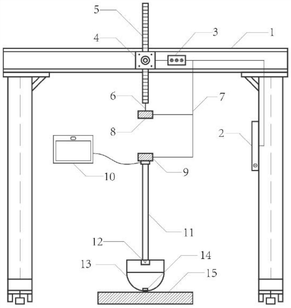
[0032] The falling ball elastic modulus tester is composed of a flange handle, a spherical crown, a host, a time difference measuring device TDC-GP2 and an acceleration sensor. The upper end of the flange handle is connected to the host, and the lower end is connected to the spherical crown. There are acceleration sensor and time difference meter TDC-GP2. When the spherical crown freely falls into contact with the soil-based material, the mechanical response parameters of its impact and collision are sent back to the host connected to the flange handle through the acceleration sensor. When the falling sphere touches the soil-based material, the time difference measuring device TDC-GP2 starts Send a pulse signal, the rebound process is over, and when the falling ball returns to the position where it initially contacts the soil foundation material, the time difference measuring device TDC-GP2 stops measuring and sends the time difference of the rebound process back to the host, a...


PUM


Abstract

According to a falling ball type rebound modulus tester, a portal frame serves as a supporting body, a linear stepping motor is installed in the center of a transverse bar of the portal frame, a driver and the linear stepping motor are connected and installed on the transverse bar, and a programmable logic controller is installed on a supporting piece at one side of the portal frame and connectedwith the driver, a first electromagnet and a second electromagnet. The first electromagnet is connected to the lower end of the linear stepping motor arm through a flexible connecting rope, the secondelectromagnet is fixed to the upper end of a flange handle of the falling ball type rebound modulus tester, and the acceleration sensor is installed at the connecting position of the flange handle and a spherical crown body; and a time difference measurer is arranged at the bottom of the spherical crown body. The tester is simple in structure, easy to install and low in cost when applied to work;and mechanical automatic measurement is realized, the measurement precision is high, and the working efficiency is improved.

Description

technical field [0001] The invention belongs to the road surface construction process. Background technique [0002] The modulus of resilience refers to the ratio of the stress generated by the subgrade, pavement and road construction materials under load to the corresponding rebound strain. The modulus of resilience is used as an indicator of the compressive strength of the soil foundation in pavement design. [0003] The state of the soil foundation is an important factor affecting the performance of the pavement. The modulus of resilience is one of the sensitive parameters for judging the state of the soil foundation. It is also a direct factor affecting the thickness of the pavement structure. When the modulus of resilience is too large, the thickness of the pavement structure will If the modulus of resilience is too small, the thickness will be too large. In addition, the deflection of the top surface of the soil foundation, the compressive strain of the top surface o...

Claims


Application Information

Patent Timeline
Patent Type & Authority Applications(China)
IPC IPC(8): G01N3/48
CPCG01N3/48G01N2203/0083
Inventor 王露婉薛瑛琪韩晓坤何华阳王梦婕王蕊
Owner RES INST OF HIGHWAY MINIST OF TRANSPORT
Learn More