Sludge cleaning device for sewage treatment

A sewage treatment and cleaning device technology, applied in the direction of water/sludge/sewage treatment, sludge treatment, grain treatment, etc., can solve problems such as the inability to effectively separate sludge and water, and improve convenience, increase storage capacity, The effect of improving adequacy

Inactive Publication Date: 2020-09-08
李燕
View PDF0 Cites 1 Cited by
  • Summary
  • Abstract
  • Description
  • Claims
  • Application Information

AI Technical Summary

Problems solved by technology

[0004] Based on the technical problem that the existing sludge cleaning device cannot realize the effective separation of sludge and water, the present invention proposes a sludge cleaning device for sewage treatment

Method used


Image

  • Sludge cleaning device for sewage treatment
  • Sludge cleaning device for sewage treatment
  • Sludge cleaning device for sewage treatment

Examples


Embodiment 1

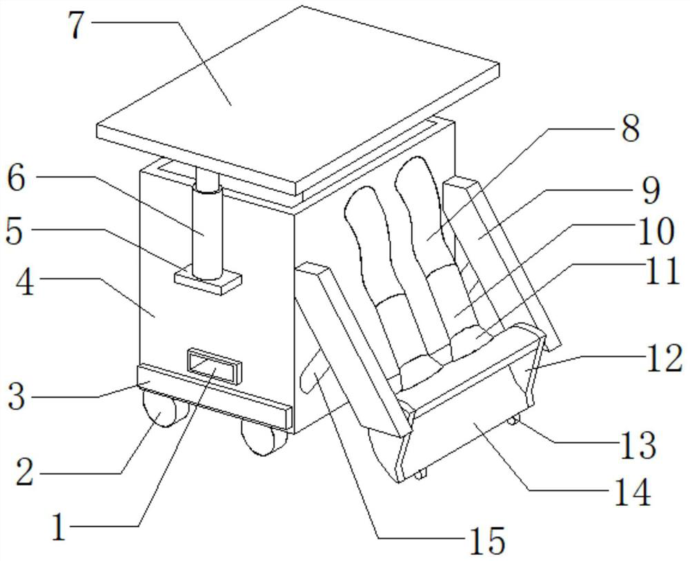
[0028] refer to Figure 1-3 , a sludge cleaning device for sewage treatment, comprising a storage box 4, the outer walls at both ends of the top of one side of the storage box 4 are connected with a second support plate 9 by hinges, and the outer walls at both ends of the bottom of one side of the storage box 4 are A hydraulic cylinder 15 is connected through a hinge, and the top outer walls of the two hydraulic cylinders 15 are respectively connected with the bottom outer walls of the two second support plates 9 through hinges, and the bottom outer walls of the adjacent sides of the two second support plates 9 are all connected by bolts. A splint 12 is connected, and the same shoveling plate 14 is connected by bolts between the two splints 12 , the outer walls at both ends of the bottom of the shoveling plate 14 are connected with rollers 13 by bolts, and the outer walls at both ends of one side of the shoveling plate 14 are connected by bolts Be connected with material gathe...

Embodiment 2

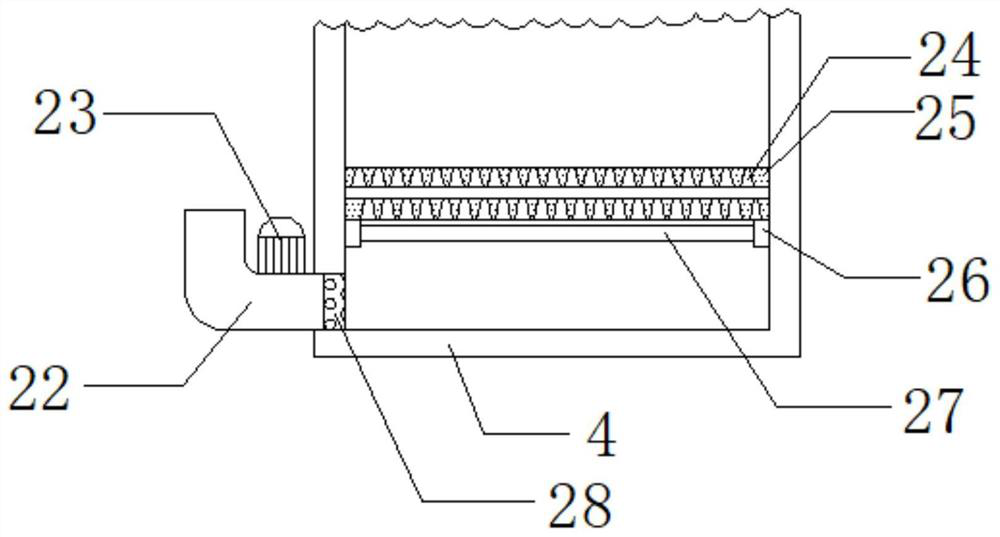
[0040] refer to Figure 1-4 , a sludge cleaning device for sewage treatment, which also includes two rotating rods 30 installed on the inner walls of the two ends of the two gathering pipes 11 through bearings, and the peripheral outer walls of the two rotating rods 30 are connected by bolts with ring-shaped arrays. Grinding teeth 29, the top outer wall of one end of the gathering pipe 11 are all connected with rotating motors by bolts, and the output shafts of the two rotating motors are respectively connected with the outer wall at one end of one of the rotating rods 30 in the two gathering pipes 11 by bolts .

[0041] When in use, during the pumping process, the rotating motor can drive the rotating rod 30 and the crushing teeth 29 to rotate, and then crush the residues of branches and leaves in the sludge, so as to avoid blocking the material guide pipe 10 and affecting the smooth pumping Therefore, the above settings can further improve the smoothness of sludge cleaning....


PUM


Abstract

The invention belongs to the technical field of sewage treatment, and particularly relates to a sludge cleaning device for sewage treatment. Aiming at the problem that an existing sludge cleaning device cannot effectively separate sludge from water, the following scheme is provided. The sludge cleaning device comprises a storage box body, wherein the outer walls of the two ends of the top of one side of the storage box body are connected with second supporting plates through hinges, the outer walls of the two ends of the bottom of one side of the storage box body are connected with hydraulic cylinders through hinges, and the outer walls of the tops of the two hydraulic cylinders are connected with the outer walls of the bottoms of the two second supporting plates through hinges respectively. According to the sludge cleaning device for sewage treatment, a third supporting plate, an inserting rod, a spring and a vibration motor are arranged at the bottom of a supporting top plate, the vibration motor can drive the third supporting plate and the inserting rod to vibrate, so that the sludge can be uniformly vibrated by the vibrating inserting rod, the storage amount is improved, and the sufficiency of uniform vibration of the sludge can be effectively improved by barbs and material guide holes in the barbs.

Description

technical field [0001] The invention relates to the technical field of sewage treatment, in particular to a sludge cleaning device for sewage treatment. Background technique [0002] Sewage treatment refers to the process of purifying sewage to meet the water quality requirements for discharge into a certain water body or reuse. Sewage treatment is widely used in various fields such as construction, agriculture, transportation, energy, petrochemical, environmental protection, urban landscape, medical treatment, catering, etc., and it is also increasingly entering the daily life of ordinary people. [0003] At present, in the sewage treatment process, a large amount of silt will be deposited on the bottom of the sewage tank. In order to clean up these silts, a sludge cleaning device will be used. The existing sludge cleaning devices will directly remove the sludge However, these silts have a large amount of water, which increases the transport weight and is inconvenient for ...

Claims


Application Information

Patent Timeline
Patent Type & Authority Applications(China)
IPC IPC(8): B08B9/087B08B15/04B02C4/08B02C4/30B02C4/42B01D21/24C02F11/121B01D29/05B01D29/56
CPCB01D21/24B01D29/05B01D29/56B02C4/08B02C4/30B02C4/42B02C2201/063B08B9/087B08B15/04C02F11/121
Inventor 李燕
Owner 李燕
Why Eureka
Try Eureka