Automatic projection welding machine

A technology of automatic rowing and welding machines, which can be applied to online nets, other household appliances, household appliances, etc., can solve the problems of different grid specifications, high manual labor intensity, welding, etc., and achieve the same length specifications before and after, and uniform and firm solder joints , The effect of specifications and quality standards

Inactive Publication Date: 2020-09-08
LAIWU IRON & STEEL GRP
View PDF10 Cites 3 Cited by
  • Summary
  • Abstract
  • Description
  • Claims
  • Application Information

AI Technical Summary

Problems solved by technology

The existing equipment has a low level of automation, and it is still necessary to manually discharge the warp and weft steel bars. The warp and weft bars need to be cut in advance for each production, and the lengths of the cuts are likely to be different. When manually putting them into the welding machine There are errors, and there are even rebar flicks that cause harm to personnel, causing welding problems, or the grids that come out have different specifications, and the specifications are different.
At the same time, there is no automatic feeding device, which also results in high labor intensity, low automatic production rate or high maintenance cost, which directly affects the benefit
Therefore, there is an urgent need to design an automatic loading, cutting, welding, and unloading welding machine to solve the problems of low automation level, poor grid quality, high labor intensity and danger, and low production efficiency.

Method used


Image

  • Automatic projection welding machine
  • Automatic projection welding machine
  • Automatic projection welding machine

Examples


Embodiment Construction

[0021] The technical solutions in the embodiments of the present invention will be described clearly and completely in further detail below in conjunction with the accompanying drawings in the embodiments of the present invention. Based on the embodiments of the present invention, all other embodiments obtained by persons of ordinary skill in the art without making creative efforts belong to the protection scope of the present invention.

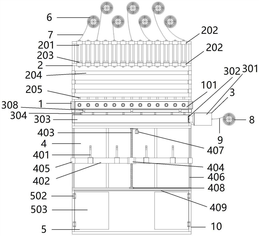
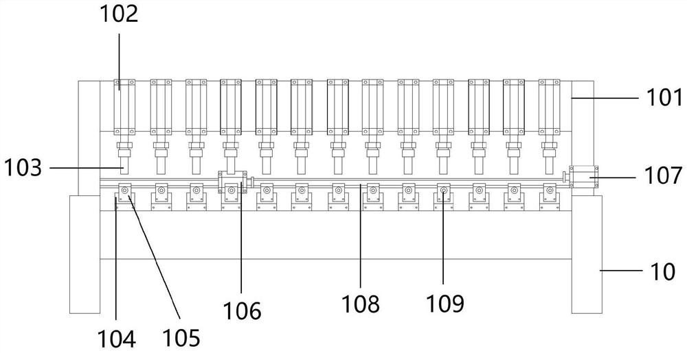
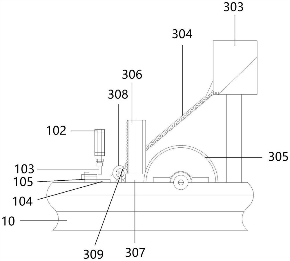
[0022] Such as Figure 1-3 As shown, an automatic welding machine includes a frame 10 and a welding device 1 installed on the frame 10, a warp thread inlet device 2, a weft thread inlet device 3, a discharge device 4 and a blanking device 5, and the warp thread Some warp wire reinforcement discs 6 provided with wire inlet device 2 are installed on the ground in rotation, and the warp wire reinforcement bars 7 wound on the warp wire reinforcement discs 6 penetrate into the rotating wire inlet pipe 201 installed on the frame, and the rotating ...


PUM


Abstract

The invention discloses an automatic projection welding machine. The automatic projection welding machine comprises a rack, a projection welding device, a warp wire inlet device, a weft wire inlet device, a discharging device and a discharging device, wherein the projection welding device, the warp wire inlet device, the weft wire inlet device, the discharging device and the discharging device areinstalled on the rack; warp steel bars wound around a warp steel bar disc penetrate into a rotary wire inlet pipe installed on the rack; wire inlet rolling shafts are distributed in an up-down staggered manner, and one end of each wire inlet rolling shaft is connected with a rolling shaft servo motor used for driving the corresponding wire inlet rolling shaft to rotate to drive wire inlet of thecorresponding warp steel bar; driven rolling wheels transfer weft steel bars to the warp steel bars between an upper electrode and a lower electrode for welding; an upward hook is arranged at the front end of a mechanical arm and used for hooking a net rack to move; a mechanical arm air cylinder controlling the mechanical arm to rotate up and down is arranged at the lower portion of the mechanicalarm; and a material cutting cutter for cutting off the net rack is arranged at the rear end of a discharging frame and used for cutting the net rack into finished net racks. According to the automatic projection welding machine, automatic feeding, cutting, welding and discharging of the warp steel bars and the weft steel bars are achieved, manpower is saved, the production efficiency is improved,unnecessary hurt to operators is avoided, and the quality of the net rack is better.

Description

technical field [0001] The invention relates to the technical field of grid production equipment, in particular to an automatic welding machine. Background technique [0002] We often see that a large number of workers are braving the scorching sun to bundle steel bars in the scorching heat, and they are still working hard on high scaffolding in the freezing cold. The efficiency of manual binding of steel mesh is low, the cost is high, the labor intensity is high, the quality is difficult to guarantee, and the working environment is harsh. With the development and progress of social economy and the wide application of mechanization, the production of steel mesh must be replaced by mechanical production instead of manual binding. Therefore, the discharge welding machine is the product of social development. The discharge welding machine, also known as the mesh welding machine, uses the high-temperature arc generated when the positive and negative poles are short-circuited in...

Claims


Application Information

Patent Timeline
Patent Type & Authority Applications(China)
IPC IPC(8): B21F27/10B21F23/00B21F27/12B21F11/00
CPCB21F11/00B21F23/00B21F27/10B21F27/12
Inventor 朱永恒王凯魏寒晨
Owner LAIWU IRON & STEEL GRP
Why Eureka
Try Eureka