Punching and discharging all-in-one machine

An all-in-one machine and frame technology, applied in drilling/drilling equipment, metal processing machinery parts, clamping, etc., can solve the problem of low efficiency of workpiece drilling and processing in small and medium-sized processing plants that are not suitable for small batch workpiece processing , complex structure of automation equipment and other issues, to achieve the effect of simple structure, improved scope of application, and low cost

Pending Publication Date: 2020-09-08
镇江市惠灵顿膜业有限公司
View PDF0 Cites 1 Cited by
  • Summary
  • Abstract
  • Description
  • Claims
  • Application Information

AI Technical Summary

Problems solved by technology

[0002] In the process of processing mechanical workpieces, most of the workpieces need to be punched, and most of the existing equipment for punching workpieces is to fix the parts on the fixture, and then move the punching mechanism or fixture so that the workpiece can be aligned with the workpiece. The punching mechanism cooperates to perform the punching operation. After the punching is completed, the fixture needs to be opened to take out the workpiece. If the workpiece is clamped and taken out manually, the punching efficiency of the workpiece will be low, and there are still The problem of high manual labor intensity
[0003] In view of the above problems, a fully automated punching processing equipment has been proposed in the prior art to realize automatic loading, clamping, punching and unloading of the workpiece by means of electric drive, although the processing of the workpiece punching has been effectively improved. efficiency, but the structure of the overall automation equipment is relatively complex, and the cost is high, it is not suitable for small batch workpiece processing or the actual use of small and medium-sized processing plants

Method used


Image

  • Punching and discharging all-in-one machine
  • Punching and discharging all-in-one machine
  • Punching and discharging all-in-one machine

Examples


Embodiment Construction

[0027] The following will clearly and completely describe the technical solutions in the embodiments of the present invention with reference to the accompanying drawings in the embodiments of the present invention. Obviously, the described embodiments are only some, not all, embodiments of the present invention. Based on the embodiments of the present invention, all other embodiments obtained by persons of ordinary skill in the art without making creative efforts belong to the protection scope of the present invention.

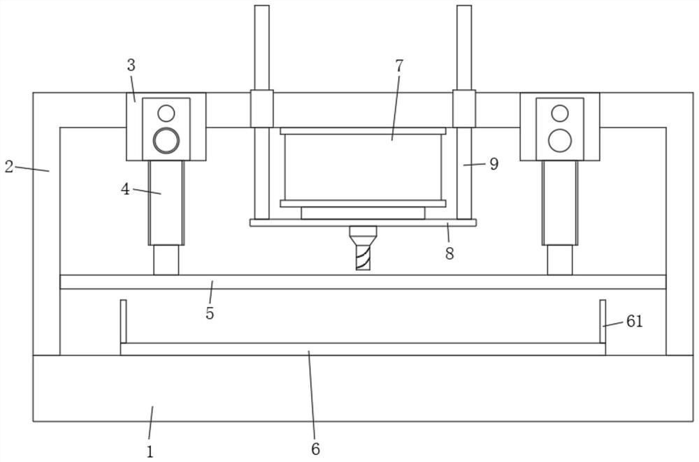
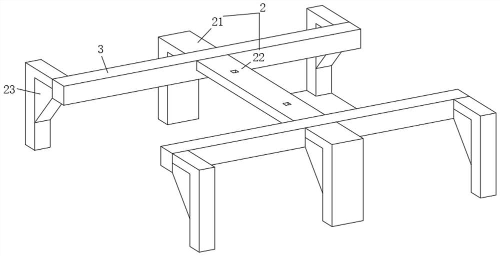
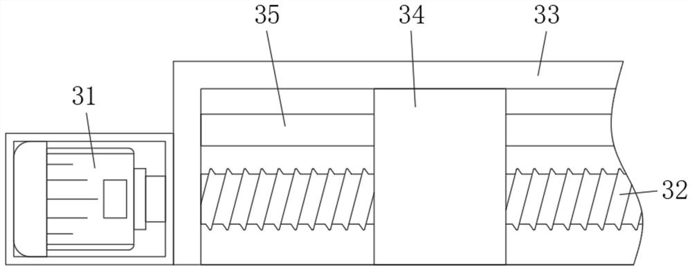
[0028] see Figure 1-Figure 6 As shown, the present invention provides the following technical solutions: a punching and blanking integrated machine, including a base 1 and a frame 2 on the top of the base 1, a punching mechanism 7 is installed in the middle of the top of the frame 2, and the machine The top of frame 2 is positioned at the both sides of punching mechanism 7 and mobile device 3 is all installed, and the bottom of two mobile devices 3 is all equ...


PUM


Abstract

The invention belongs to the technical field of machining, and discloses a punching and discharging all-in-one machine. The punching and discharging all-in-one machine comprises a base and a rack, wherein a punching mechanism is installed in the middle of the top of the rack; moving devices are installed at the positions, positioned on the two sides of the punching mechanism, of the top of the rack; lifting air cylinders are installed at the bottoms of the two moving devices; an upper pressing plate is connected to the bottoms of the two lifting air cylinders; a guide hole and two limiting grooves are formed in the upper pressing plate; the two limiting grooves are symmetrically positioned in the two sides of the guide hole; a movable lower pressing plate is arranged at the top of the base; limiting blocks are vertically fixed to the two sides of the lower pressing plate; and the limiting blocks correspond to the limiting grooves. According to the punching and discharging all-in-one machine, an automatic discharging structure of a workpiece is arranged, and therefore automatic discharging can be effectively formed after punching of the workpiece is completed; and the automatic discharging structure is composed of the movable lower pressing plate and a plurality of discharging rollers, and the punching and discharging all-in-one machine has the beneficial effects of being simplein structure and low in cost.

Description

technical field [0001] The invention belongs to the technical field of mechanical processing, and in particular relates to a punching and blanking integrated machine. Background technique [0002] In the process of processing mechanical workpieces, most of the workpieces need to be punched, and most of the existing equipment for punching workpieces is to fix the parts on the fixture, and then move the punching mechanism or fixture so that the workpiece can be aligned with the workpiece. The punching mechanism cooperates to perform the punching operation. After the punching is completed, the fixture needs to be opened to take out the workpiece. If the workpiece is clamped and taken out manually, the punching efficiency of the workpiece will be low, and there are still The problem of high manual labor intensity. [0003] In view of the above problems, a fully automated punching processing equipment has been proposed in the prior art to realize automatic loading, clamping, pun...

Claims


Application Information

Patent Timeline
Patent Type & Authority Applications(China)
IPC IPC(8): B23B47/00B23Q3/06B23Q7/05
CPCB23B47/00B23Q3/06B23Q7/055
Inventor 步建忠
Owner 镇江市惠灵顿膜业有限公司
Why Eureka
Try Eureka