Full-automatic numerically controlled machine tool and control method thereof
A CNC machine tool, fully automatic technology, applied in the field of CNC machine tools, can solve the problems of easily damaged workpieces, scrapped parts, and the inability to meet the work requirements of workpieces one by one, and achieve the effect of expanding the scope of application and ensuring stability
- Summary
- Abstract
- Description
- Claims
- Application Information
AI Technical Summary
Problems solved by technology
Method used
Image


Examples
Embodiment 1
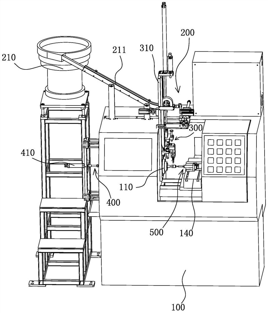
[0049] Such as figure 1 — Figure 5 , Figure 7 and Figure 9 As shown, a fully automatic CNC machine tool of the present invention includes a casing 100 , a clamping platform 110 , a workbench 140 , a feeding mechanism 200 , a clamping mechanism 300 , a left feeding mechanism 400 and a right feeding mechanism 500 .
[0050]The casing 100 is provided with a clamping table 110 and a workbench 140, and the casing 100 is provided with a feeding mechanism 200; the clamping mechanism 300 is installed in the casing 100, and the clamping mechanism 300 can be raised and lowered relative to the casing 100; The mechanism 400 is installed in the casing 100, the left feeding mechanism 400 moves through the clamping platform 110, the right feeding mechanism 500 is installed on the workbench 140, the right feeding mechanism 500 can move relative to the workbench 140, the central axis of the left feeding mechanism 400 Coinciding with the central axis of the right feeding mechanism 500, a ...
Embodiment 2
[0062] Such as Figure 8 As shown, the difference between this embodiment and Embodiment 1 is that this embodiment changes part of the structures of the left feeding mechanism 400 and the right feeding mechanism 500 .
[0063] Specifically, one end of the fourth moving rod 411 is provided with a plurality of claws 440 in a circular array along its central axis, one end of the fifth moving rod 511 is provided with a moving block 540, and the moving block 540 is provided with a pair of long rods 541 and a For the short rods 542, two long rods 541 are symmetrical to the center of the moving block 540, two short rods 542 are symmetrical to the center of the moving block 540, and the circumferential angle between the long rods 541 and the adjacent short rods 542 is a right angle.
[0064] When the two grippers 323a clamp the workpiece between the fourth moving rod 411 and the fifth moving rod 511, the fourth cylinder 410 pushes the fourth moving rod 411 and the plurality of jaws 44...
Embodiment 3
[0067] Such as Figure 5 and Figure 6 As shown, the difference between this embodiment and the first embodiment is that this embodiment adds a positioning component 600 on the basis of the first embodiment.
[0068] The fixed plate 310 is provided with a positioning assembly 600 corresponding to the feeding mechanism 200. The positioning assembly 600 can pass through the fixed plate 310. Specifically, the positioning assembly 600 includes a positioning rod 610 that is movable through the mounting plate 310 and is used to drive the positioning rod. 610 moves the fourth cylinder 620, the fixed plate 310 is detachably connected with a fixed block 630, the fixed block 630 is connected with a mounting plate 640 for installing the fourth cylinder 620, the fourth cylinder 620 is provided with a fourth push Rod 621, the fourth push rod 621 is provided with an engaging plate 650 for connecting the positioning rod 610. During installation, people need to install the fourth cylinder 62...
PUM
 Abstract
Description
Claims
Application Information