Precise punching equipment for router plastic shell

A technology of plastic shell and punching equipment, applied in metal processing equipment, grinding/polishing equipment, grinder, etc., can solve the problem of low precision of manual drilling, and achieve the convenience of manual observation, ensure accuracy, and improve work safety. Effects of Sex and Convenience

Pending Publication Date: 2020-09-11
昆山六二丰塑胶电子有限公司
View PDF0 Cites 2 Cited by
  • Summary
  • Abstract
  • Description
  • Claims
  • Application Information

AI Technical Summary

Problems solved by technology

[0004] The present invention aims at the above-mentioned deficiencies in the prior art, and provides a precision drilling equipment for the plastic shell of a router. The position of the product and the operation of the drilling mechanism and the grinding mechanism are controlled by the controller, and the precise drilling of the router shell is realized. On the one hand, drilling through equipment improves the speed and accuracy of drilling, on the other hand, reduces the scrap rate, improves profits, solves the problems of low precision and high cost of manual drilling, and saves labor; in addition, grinding The mechanism can grind the hole position, remove burrs, and improve product quality

Method used


Image

  • Precise punching equipment for router plastic shell
  • Precise punching equipment for router plastic shell
  • Precise punching equipment for router plastic shell

Examples


Embodiment 1

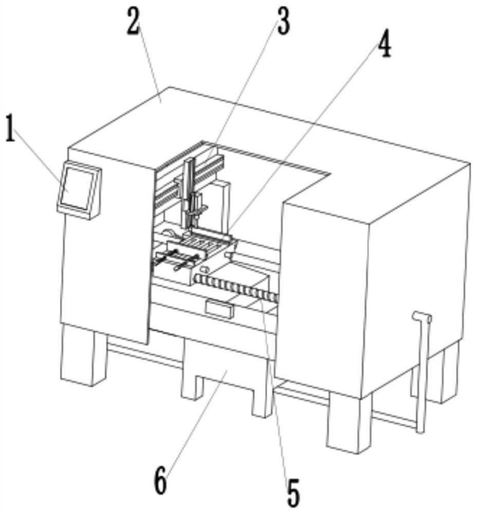
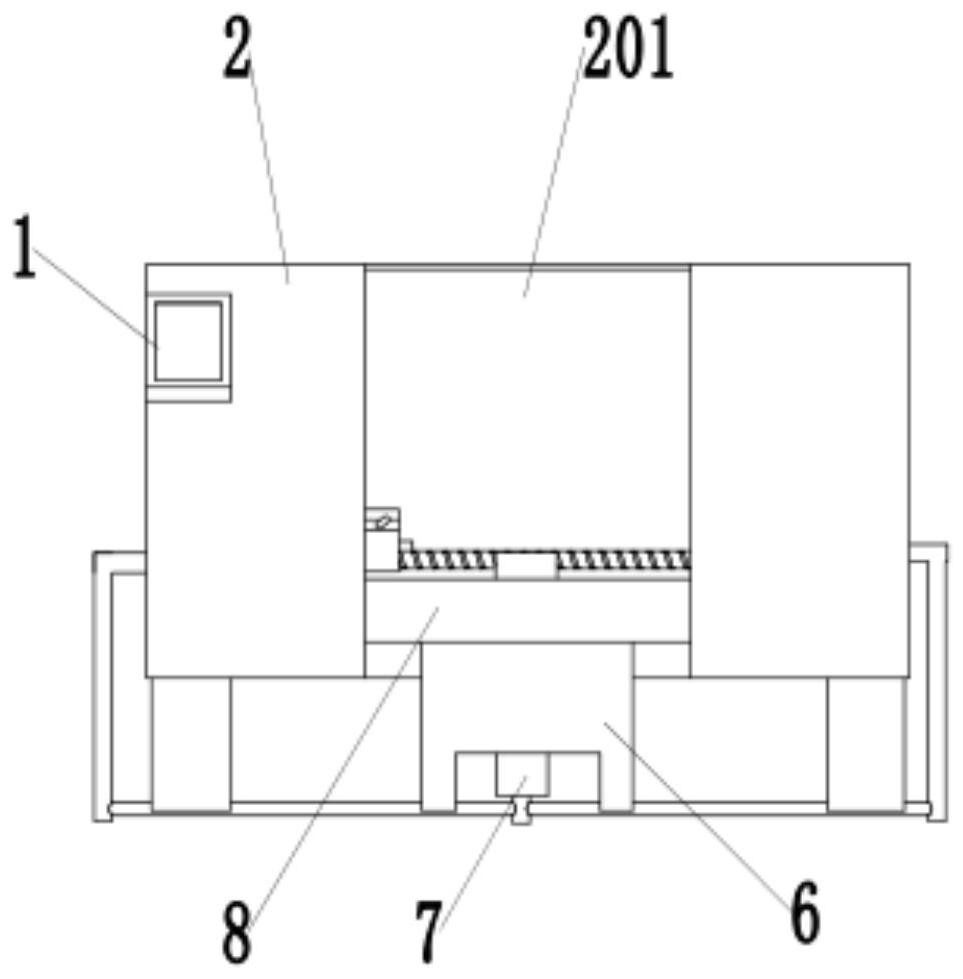
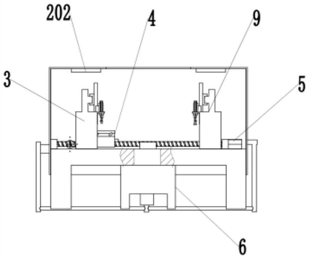
[0035] Such as Figure 1-4 As shown, a router plastic casing precision drilling equipment, including a controller 1, a machine cover 2, a drilling mechanism 3, a driving mechanism 5, a workbench 8 and a grinding mechanism 9, the upper end of the workbench 8 is provided with a drive mechanism 5 , the driving mechanism 5 is provided with a punching table 4 that slides left and right along a straight line, the punching table 4 is provided with a blanking hole 411, and the debris after punching falls from the blanking hole 411, and the two ends of the driving mechanism 5 A drilling mechanism 3 and a grinding mechanism 9 connected to the workbench 8 are provided. The drilling mechanism 3 and the grinding mechanism 9 are located above the punching table 4. The upper end of the workbench 8 is covered with a machine cover 2, and the middle part of the machine cover 2 is provided with a The hole 201 for placing the product is convenient, the drilling mechanism 3 and the grinding mechan...

Embodiment 2

[0045] In order to further ensure the operation safety of workers;

[0046] Such as Figure 5 As shown, the upper end of the workbench 8 is provided with an infrared sensor 803 electrically connected to the controller 1. The infrared sensor 803 is located at the hole 201. When the infrared sensor 803 detects a human body, the device will not start to ensure safety.

Embodiment 3

[0048] Such as image 3 , 5 As shown, in order to improve the thoroughness of waste cleaning, a fan 7 is provided below the waste box 6, and a flat air outlet 701 is provided on the inner side of the first fixed plate 502 and the second fixed plate 505, and the air outlet The mouth 701 is connected with the blower 7 through the air pipe, and the debris is blown into the collection hole 802 by the blower 7, which saves cleaning time.


PUM


Abstract

The invention discloses precision punching equipment for a router plastic shell. The precise punching equipment for the router plastic shell comprises a controller, a machine cover, a drilling mechanism, a driving mechanism, a workbench and a grinding mechanism, wherein the driving mechanism is arranged at the upper end of the workbench, a punching table sliding left and right along a straight line is arranged on the driving mechanism, a blanking hole is formed in the punching table, and the drilling mechanism and the grinding mechanism which are connected with the workbench are arranged at the two ends of the driving mechanism; the upper end of the workbench is sleeved with the machine cover, a workpiece placing hole facilitating product taking and placing is formed in the middle of the machine cover, the controller is arranged on the outer side of the machine cover, and the controller is electrically connected with the drilling mechanism, the driving mechanism and the grinding mechanism; and a waste chip collecting hole is formed in the workbench, and a waste chip box is connected below the waste chip collecting hole. The precision punching equipment for the router plastic shellhas the following beneficial effects that the problems that existing manual drilling is low in precision and high in cost are solved, and labor is saved; and in addition, the grinding mechanism can grind a hole site, burrs are removed, and the product quality is improved.

Description

technical field [0001] The invention relates to the technical field of router shell processing, in particular to precision drilling equipment for router plastic shells. Background technique [0002] A router is a hardware device that connects two or more networks. It acts as a gateway between networks. It is a dedicated intelligent network device that reads the address in each data packet and then decides how to transmit it. It can understand different protocols, such as the Ethernet protocol used by a local area network, and the TCP / IP protocol used by the Internet. In this way, the router can analyze the destination addresses of data packets from various types of networks, and convert the addresses of non-TCP / IP networks into TCP / IP addresses, or vice versa; The best route is sent to the designated location. [0003] The current router casing is generally made of plastic material, and the casing is divided into upper and lower parts, which are connected by bolts. The ass...

Claims


Application Information

Patent Timeline
Patent Type & Authority Applications(China)
IPC IPC(8): B26F1/16B26D7/02B26D7/18B26D7/22B26D7/27B26D7/00B24B9/20
CPCB24B9/20B26D7/00B26D7/02B26D7/1854B26D7/22B26D7/27B26D2007/0018B26F1/16
Inventor 汪新著
Owner 昆山六二丰塑胶电子有限公司
Why Eureka
Try Eureka