Sewing machine

A technology for sewing machines and driving motors, which is applied to sewing machine components, sewing machine control devices, sewing equipment, etc. It can solve the problems of feeding teeth colliding with the needle plate, noise, and large changes in needle pitch, so as to avoid collisions of parts and simplify electrical wiring. control program, occupying a small volume effect

Active Publication Date: 2020-09-11
JACK SEWING MASCH CO LTD
View PDF11 Cites 26 Cited by
  • Summary
  • Abstract
  • Description
  • Claims
  • Application Information

AI Technical Summary

Problems solved by technology

However, the use of the avoidance mechanism with the above-mentioned structure in the stitch-gauge adjustment part that requires relatively high working conditions will cause the following problems: the stitch-gauge adjustment mechanism cannot respond in time due to the tension spring when switching the stitch length at high speed; There will be collision phenomenon in the avoidance mechanism, which will generate ...

Method used


Image

  • Sewing machine
  • Sewing machine
  • Sewing machine

Examples


Embodiment 1

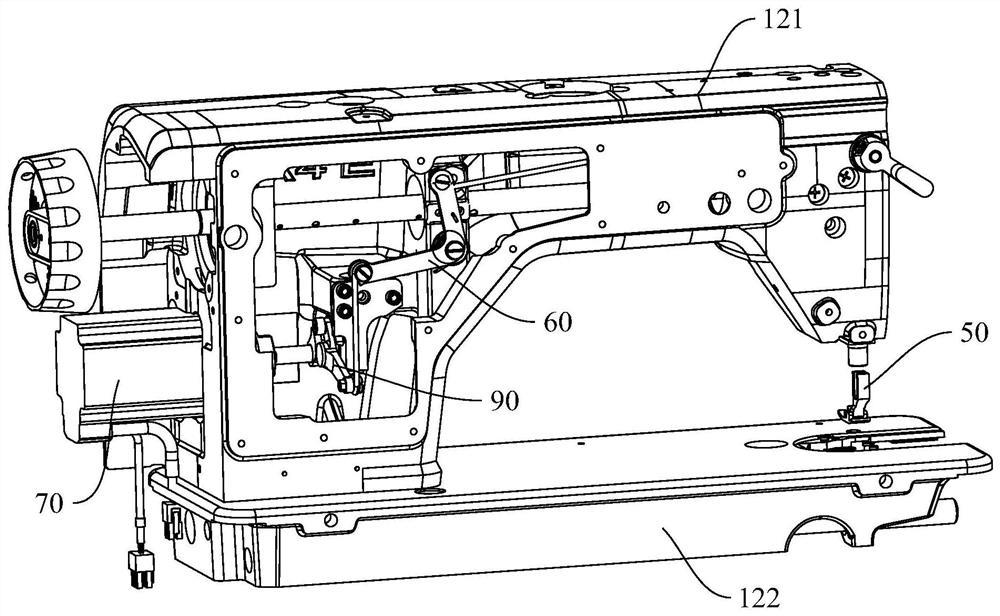
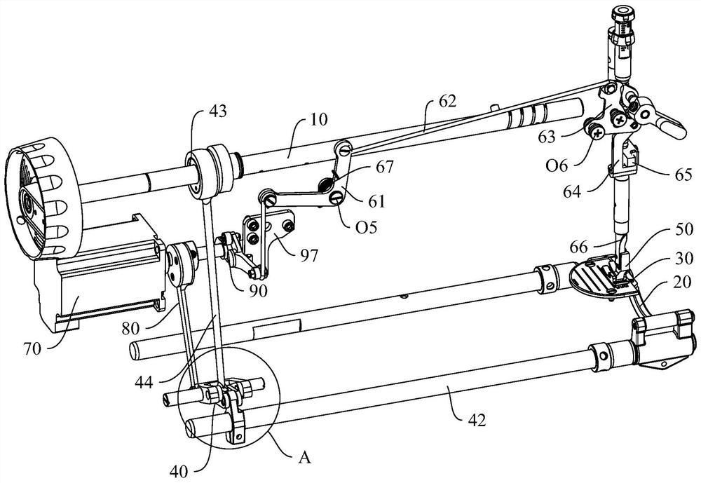
[0128] Such as figure 1 and figure 2 As shown, except that the sewing machine includes the main shaft 10 extending left and right, the sewing machine also includes a tooth frame 20, a feed dog 30 fixedly installed on the tooth frame 20, a feeding mechanism 40 connected between the main shaft 10 and the front end of the tooth frame 20, and a press. The pin 50, the presser foot lifting mechanism 60 connected to the presser foot 50, the drive motor 70, the needle pitch power transmission mechanism 80 connected between the output shaft of the drive motor 70 and the feeding swing seat 41, and the drive motor 70 The presser foot lifting transmission mechanism 90 between the output shaft and the presser foot lifting mechanism 60, the feeding mechanism 40 has a feeding swing seat 41 that can rotate around the first fixed swing fulcrum O1, and the angle of the feeding swing seat 41 determines the needle pitch of the sewing machine. The needle pitch power transmission mechanism 80 ena...

Embodiment 2

[0155] The difference between the second embodiment of the sewing machine and the first embodiment of the sewing machine is that in the first embodiment of the sewing machine, the transmission eccentric wheel 81 and the transmission cam 91 are two independent parts, which are respectively fixed on the output shaft of the driving motor 70 by screws; In the second example, the transmission eccentric wheel 81 and the transmission cam 91 are combined into an integrated structure, such as Figure 18 and Figure 19 shown.

Embodiment 3

[0157] The difference between the third embodiment of the sewing machine and the first embodiment of the sewing machine lies in the specific structure of the power transmission mechanism 80 for adjusting the needle distance. In the third embodiment of the sewing machine, the structure of the fork-shaped transmission link 83 is adopted. Specifically, if Figure 20 to Figure 22 As shown, the stitch adjustment power transmission mechanism 80 in the third embodiment of the sewing machine includes a transmission eccentric 81, a fork-shaped transmission connecting rod 83, and a first connecting rod 84 with a second fixed swing fulcrum O2 at one end. The transmission eccentric 81 passes through The screw is fixed on the output shaft of the driving motor 70. The upper end of the fork-shaped transmission link 83 is a fork-shaped part with a first chute 831. The fork-shaped part is in rotation and sliding fit with the transmission eccentric wheel 81. The fork-shaped transmission link Th...


PUM


Abstract

The invention provides a sewing machine. The sewing machine comprises a main shaft, a material feeding mechanism, a presser foot lifting mechanism, a driving motor, a needle pitch adjusting power transmission mechanism and a presser foot lifting transmission mechanism, wherein the material feeding mechanism is provided with a material feeding swinging seat; the needle pitch adjusting power transmission mechanism enables power transmission to continuously exist between the driving motor and the material feeding swinging seat; a collision avoidance structure is arranged in the presser foot lifting transmission mechanism; a corner of an output shaft of the driving motor is provided with a needle pitch active adjusting area and a presser foot lifting area; when the output shaft of the drivingmotor operates within the needle pitch active adjusting area, the sewing machine is provided with effective needle pitch; the collision avoidance structure enables no power transmission to exist between the driving motor and a presser foot lifting mechanism; when the output shaft of the driving motor operates within the presser foot lifting area, the presser foot lifting transmission mechanism enables power transmission to exist between the driving motor and the presser foot lifting mechanism; and the absolute value of a needle pitch corresponding to an angle of the material feeding swinging seat is not larger than a maximum absolute value of the effective needle pitch. According to the sewing machine, timely response, suspended seam and very good needle pitch adjusting stability of the needle pitch adjusting mechanism are realized.

Description

technical field [0001] The present invention relates to a sewing machine. Background technique [0002] At present, the sewing machine is provided with a main motor, a main shaft connected to the motor shaft of the main motor, a tooth frame, a feeding tooth installed on the tooth frame, a feeding mechanism connected between the main shaft and one end of the tooth frame, and a tooth frame connected between the main shaft and the tooth frame. The tooth lifting mechanism between the other ends of the rack, the presser foot, and the presser foot lifting mechanism connected with the presser foot, the main shaft drives the tooth frame and the feeding dog to perform a compound motion of back and forth reciprocating motion and up and down reciprocating motion through the feeding mechanism and the tooth lifting mechanism. The trajectory of the feed tooth is elliptical. [0003] Further, the structure of the presser foot lifting mechanism can be referred to a sewing machine disclosed...

Claims


Application Information

Patent Timeline
IPC IPC(8): D05B27/22D05B29/02D05B69/10
CPCD05B27/22D05B29/02D05B69/10
Inventor 何明金祝书伟柯祥林郑吉
Owner JACK SEWING MASCH CO LTD
Why Eureka
Try Eureka