Shock absorber

A shock absorber and working cylinder technology, which is applied in the field of machinery, can solve problems such as insufficient adaptability of shock absorbers, and achieve the effects of stable use, improved stability, and guaranteed stability and reliability

Pending Publication Date: 2020-09-11
台州九桔科技股份有限公司
View PDF1 Cites 2 Cited by
  • Summary
  • Abstract
  • Description
  • Claims
  • Application Information

AI Technical Summary

Problems solved by technology

[0006] The purpose of the present invention is to propose a shock absorber for the above-mentioned problems existing

Method used


Image

  • Shock absorber
  • Shock absorber
  • Shock absorber

Examples


Embodiment 1

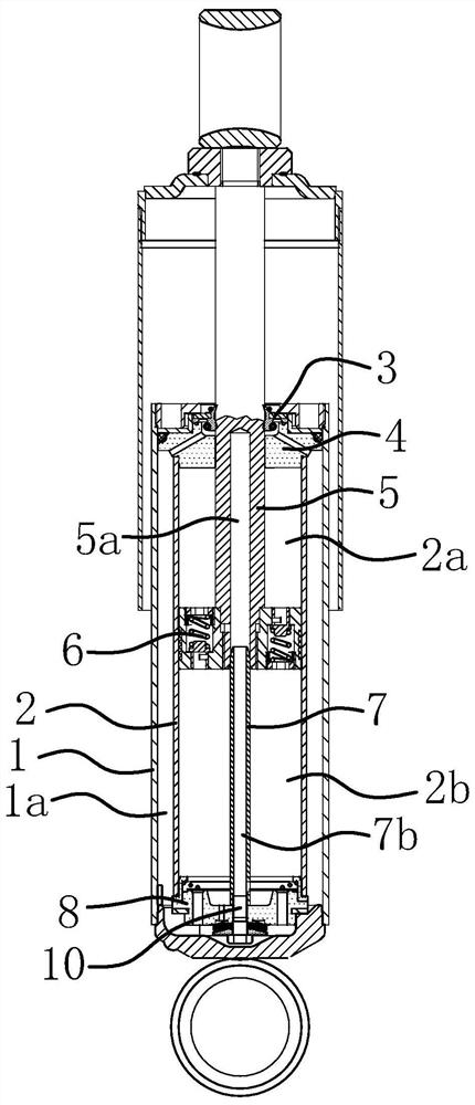
[0047] Such as Figure 1-Figure 3 As shown, a shock absorber includes an oil storage cylinder 1 and a working cylinder 2 arranged in the oil storage cylinder 1. There is an oil storage chamber 1a between the outer surface of the working cylinder 2 and the inner surface of the oil storage cylinder 1. The oil storage cylinder 1 The top end is fixed with an oil seal 3 and a guide 4, the top of the working cylinder 2 is connected to the guide 4, a bottom valve 8 is arranged between the bottom end of the working cylinder 2 and the bottom end of the oil storage cylinder 1, and the inner cavity of the working cylinder 2 A movable piston rod 5 is provided, and the top end of the piston rod 5 extends out of the top end of the oil storage cylinder 1 after passing through the guide 4 and the oil seal 3, and the bottom end of the piston rod 5 is fixed with a piston assembly 6, and the piston assembly 6 will work The inner chamber of the cylinder 2 is divided into a top chamber 2a and a bo...

Embodiment 2

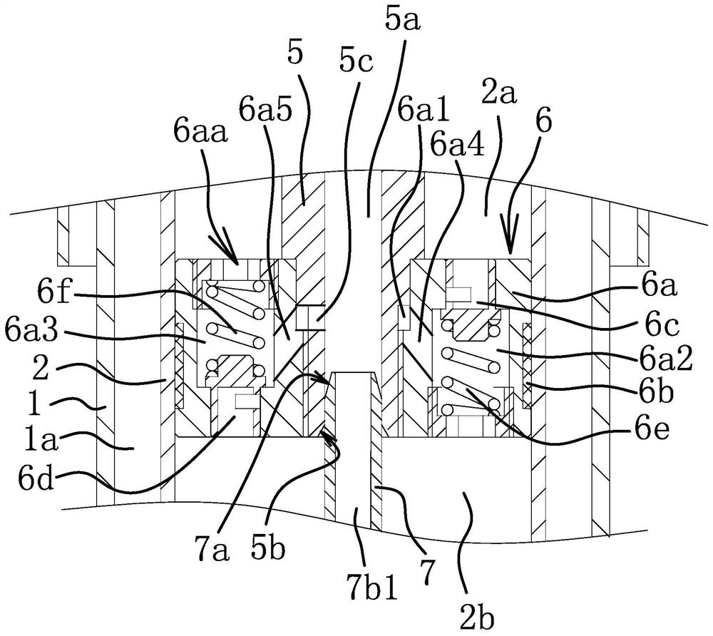
[0057] The structure of the backflow channel 7b is different from that of Embodiment 1. The backflow channel 7b includes a long groove arranged on the outer surface of the valve stem 7. The top end of the long groove runs through the top surface of the valve stem 7, and the bottom end of the long groove extends to the bottom of the valve stem 7. bottom.

[0058] The flow passage 6aa is different from the first embodiment. The flow passage 6aa includes an axial hole that runs through the top end surface of the piston body 6a and the bottom end surface of the piston body 6a. The inner surface of the piston body 6a is provided with a radial hole, and the radial hole is connected to the shaft. It is connected to the hole, and the radial hole is connected with the throttle hole 5c. The diameter of the radial hole is larger than or equal to the throttle hole 5c. The diameter of the axial hole is larger than the diameter of the throttle hole 5c. The diameter of the axial hole is large...


PUM


Abstract

The invention provides a shock absorber, and belongs to the technical field of machines. According to the shock absorber, the problems of insufficient self adaptability of an existing shock absorber and the like are solved. The shock absorber comprises a working cylinder, a movable piston rod is arranged in the working cylinder, a piston assembly is fixedly connected to the piston rod, the inner cavity of the working cylinder is divided into a top cavity and a bottom cavity by the piston assembly, an inserting hole is formed in the bottom end surface of the piston rod, a flow passing channel communicating the top cavity with the bottom cavity is formed in the piston assembly, a flow restriction hole communicating with the flow passing channel is formed in the hole wall surface of the inserting hole, a valve rod which can be inserted into and pulled out of the inserting hole is fixed to the bottom of the working cylinder, when the valve rod is inserted into the inserting hole, the outerside surface of the valve rod is in fit with the hole wall of the inserting hole in a matched mode, and the valve rod can block the flow restriction hole, and a reflux channel which is used for communicating the inserting hole with the bottom cavity when the valve rod is inserted into the inserting hole is formed in the valve rod. According to the shock absorber, the self adaptability is improved, and working is stable.

Description

technical field [0001] The invention belongs to the technical field of machinery and relates to a shock absorber. Background technique [0002] The bogie is a device that supports the car body and makes it run on the track. It is also called the running part and is the key component of the rail car. Driving device and foundation brake device, etc. Multiple shock absorbers are installed on the rail car bogie to control vibration. There are many kinds of shock absorbers, which can be divided into hydraulic type and pneumatic type from the material point of view, and can be divided into single-tube type and double-tube type from the structural point of view. Railcar shock absorbers are generally double-tube hydraulic shock absorbers. [0003] Chinese patent documents disclose a hydraulic shock absorber for high-speed railway vehicles [application number: CN201020113086.6; announcement number: CN201651150U], which consists of a dust cover, a working cylinder, a piston rod, an ...

Claims


Application Information

Patent Timeline
IPC IPC(8): F16F9/19F16F9/34F16F9/36F16F9/49
CPCF16F9/185F16F9/49F16F9/3405F16F9/366F16F9/486
Inventor 项文峰李超汪宏涛张烁
Owner 台州九桔科技股份有限公司
Why Eureka
Try Eureka