
Double-joint loading power servo knife rest power head reliability test bed and test method

A technology of servo tool post and combined loading, which is applied in the testing of mechanical components, testing of machine/structural components, instruments, etc., can solve the problems that the combined loading and spraying of power heads cannot be simulated, and achieve real-time monitoring and closed-loop control And feedback, the effect of high loading accuracy

Pending Publication Date: 2020-09-11
JILIN UNIV
View PDF0 Cites 4 Cited by
  • Summary
  • Abstract
  • Description
  • Claims
  • Application Information

AI Technical Summary

Problems solved by technology

[0004] The purpose of the present invention is to solve the above-mentioned technical problems, overcome the problem that the current power servo tool holder reliability test device cannot simulate the joint loading and spraying of the power head, and provide a power servo tool holder power head joint loading reliability test bench and experiment method

Method used


Image

  • Double-joint loading power servo knife rest power head reliability test bed and test method
  • Double-joint loading power servo knife rest power head reliability test bed and test method
  • Double-joint loading power servo knife rest power head reliability test bed and test method

Examples


Embodiment 1

[0069] Example 1 Reliability test bench for dual combined loading power servo tool holder power head

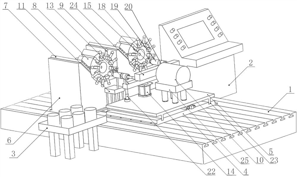
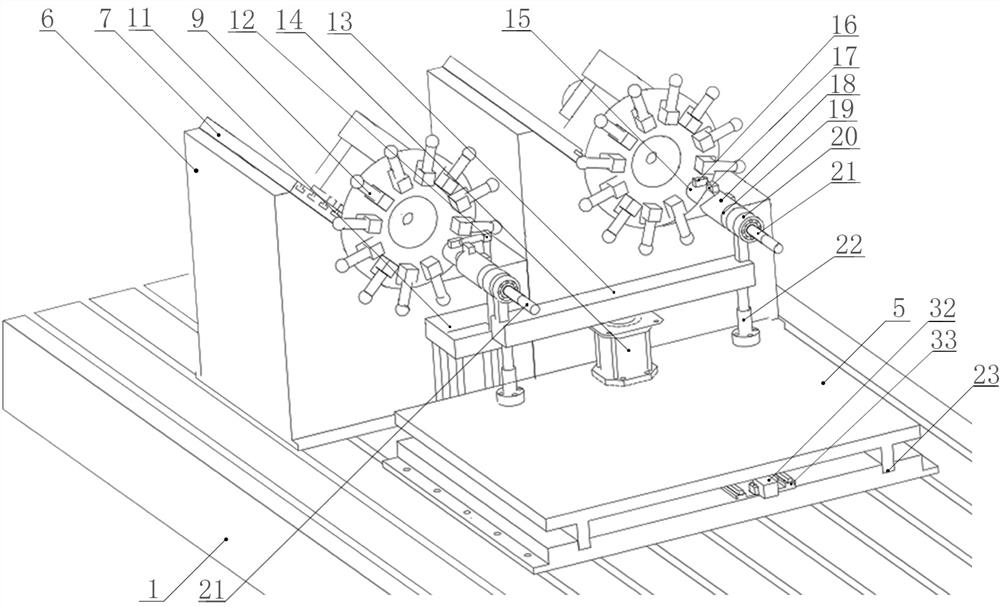
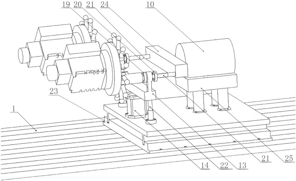
[0070] see Figure 1 to Figure 5 As shown in the figure, the reliability test bench for the power head of the double combined loading power servo tool holder includes: ground level iron 1, the part of the power servo tool holder, the loading part of the power head, the spray system part, the dynamometer part, and the detection control part;

[0071] The horizontal iron 1 is a solid cast iron structure, and the upper surface is provided with T-shaped grooves parallel to each other;

[0072] The power servo tool holder part includes: a power servo tool holder base 6, a power servo tool holder backing plate 7, a power servo tool holder 8, a simulated tool holder 9 and a power head 15;

[0073] The power servo tool rest base 6 adopts an integral casting with a polygonal hollow structure; the bolts are installed in the T-shaped groove of the horizontal iron 1, and the bottom of t...

Embodiment 2

[0101] Example 2 Reliability test method of double combined loading power servo tool holder power head

[0102] The method for testing the reliability of the power head of the double joint loading power servo tool holder according to the present invention adopts the reliability test bench for the power head of the double joint loading power servo tool holder described in Embodiment 1, and provides a power servo tool holder for the tested piece. A set of reliability test methods;

[0103] refer to Image 6 and Figure 7 , the reliability test of the power head of the power servo tool holder with double joint loading mainly includes the indexing test of the power servo tool holder and the joint loading test of the power head. The specific method steps are as follows:

[0104] 1. Indexing test of the dynamic servo tool post

[0105] 1) Keep the temperature of the test environment constant at 20 degrees Celsius, and place the test bench in the test environment for more than 12 ...


PUM


Abstract

The invention discloses a double-joint loading power servo knife rest power head reliability test bed and a test method. The test bed comprises horizontal iron, a power servo knife rest part, a powerhead loading part, a spray cooling system part, a dynamometer part, a detection control part and a hydraulic pump part. The power servo knife rest part comprises two power servo knife rest bases, twopower servo knife rests, a simulation knife bar and a power head; the same loading device can be used for carrying out jointloading on the double-knife-rest power head, the magnitude of loading forcecan be freely adjusted by adopting the servo hydraulic cylinder, and the stress is uniform; a dynamometer and a loading device are installed during torque loading and rotating speed measurement, real-time monitoring and closed-loop control can also be achieved on the loaded cutting torque and rotating speed, and the loading device has high loading precision.

Description

technical field [0001] The invention relates to the field of a reliability test device applied to the power servo tool holder of a numerical control machine tool. Torque loading, spraying and data detection, combined with dynamometer, hydraulic mixed loading, spraying device, operating table and sensors, the reliability test bench and test method of the double combined loading power servo tool holder power head. Background technique [0002] In recent years, with the rapid development of the equipment manufacturing industry, my country has become a big country in the production and application of CNC machine tools. At present, the domestically developed CNC machine tools have made significant progress in precision, speed, large-scale and multi-axis linkage; The increase in the number of failures, the increase in hidden dangers, the inability to maintain advanced functions and performance indicators, and serious reliability problems have become the focus of attention of enterp...

Claims


Application Information

Patent Timeline
IPC IPC(8): G01M13/00
CPCG01M13/00
Inventor 罗巍黄昊刘明何佳龙刘新东焦雷胡炜王志达王子月苏肇明姚荣麟
Owner JILIN UNIV
Learn More