
Power measurement equipment adopting power line carrier technology

A technology of power measurement and power carrier, which is applied in the field of power measurement equipment using power carrier technology, can solve problems such as inability to alarm, cumbersome structure, and inconvenient opening and closing for users, so as to facilitate opening and closing, reduce safety hazards, Avoid bad contact effects

Inactive Publication Date: 2020-09-11
杨毕女
View PDF0 Cites 0 Cited by
  • Summary
  • Abstract
  • Description
  • Claims
  • Application Information

AI Technical Summary

Problems solved by technology

[0004] The purpose of the present invention is to provide a power measurement device using power carrier technology to solve the inconvenience of positioning the power measurement device proposed in the background technology during initial installation, which brings inconvenience to subsequent fixation, cumbersome structure, and inconvenient operation. It is inconvenient for the user to use, and it is inconvenient for the user to conveniently open and close some components of the measuring equipment according to the needs of the use during use, and it is not possible to perform timely alarm processing in the event of a fire, which has potential safety hazards and is inconvenient to use. The problem of limit protection for some connecting wires in power measuring equipment

Method used


Image

  • Power measurement equipment adopting power line carrier technology
  • Power measurement equipment adopting power line carrier technology
  • Power measurement equipment adopting power line carrier technology

Examples


Embodiment Construction

[0026] The following will clearly and completely describe the technical solutions in the embodiments of the present invention with reference to the accompanying drawings in the embodiments of the present invention. Obviously, the described embodiments are only some, not all, embodiments of the present invention. Based on the embodiments of the present invention, all other embodiments obtained by persons of ordinary skill in the art without making creative efforts belong to the protection scope of the present invention.

[0027] In the description of the present invention, unless otherwise stated, the meaning of "plurality" is two or more; the terms "upper", "lower", "left", "right", "inner", "outer" , "front end", "rear end", "head", "tail", etc. indicate the orientation or positional relationship based on the orientation or positional relationship shown in the drawings, and are only for the convenience of describing the present invention and simplifying the description, rather...


PUM


Abstract

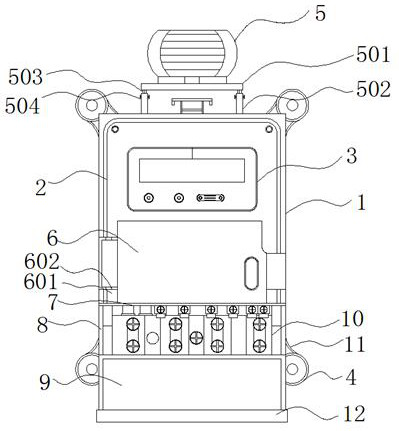
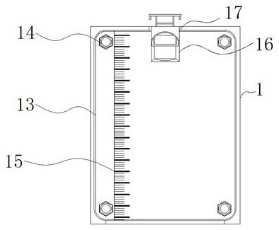
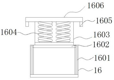
The invention discloses power measurement equipment adopting a power line carrier technology, and relates to the technical field of electric power measurement. The power measurement equipment comprises a main body and a fastening bolt, a front cover shell is arranged outside the front end of the main body, a display assembly is installed inside the front cover shell, an auxiliary device is arranged outside the bottom of the front cover shell, a clamping groove is formed outside the bottom of the auxiliary device, and a connecting assembly is arranged outside the bottom of the clamping groove.According to the invention, the alarm device, the connecting plate, the fixed rod, the movable rod and the fixed bolt are arranged; the alarm device is a smoke alarm, timely alarm processing can be carried out when a fire occurs in the electric power measurement equipment; damage is reduced, potential safety hazards are reduced, the placement height of the connecting plate can be properly adjustedthrough the interaction of the fixed rod, the movable rod and the fixed bolt according to the environment installation requirement of the electric power measurement equipment, the structure is simple, use is flexible, and a user can conveniently and rapidly operate the electric power measurement equipment.

Description

technical field [0001] The invention relates to the technical field of power measurement, in particular to a power measurement device using power carrier technology. Background technique [0002] Measurement is to use data to describe the observed phenomenon according to a certain law, that is, to make a quantitative description of things. Measurement is the process of quantifying non-quantified objects. Electric energy meters are used in the construction of electric power. Electric energy meters are instruments used to measure electric energy, also known as watt-hour meters, fire meters, and kilowatt-hour meters, which refer to instruments that measure various electrical quantities. [0003] The power measurement equipment on the market is inconvenient to locate during the initial installation, which brings inconvenience to the subsequent fixation. The convenient opening and closing of the components and the inability to perform timely alarm processing in the event of a f...

Claims


Application Information

Patent Timeline
IPC IPC(8): G01R11/00G01R11/02G01R11/04G08B17/10H02J13/00
CPCG01R11/00G01R11/02G01R11/04G08B17/10H02J13/00007
Inventor 杨毕女
Owner 杨毕女
Learn More