Structure for improving return loss and application

A return loss, integrated technology, applied in the field of optical communication, can solve the problem of mutual restriction of return loss, and achieve the effect of improving return loss, avoiding reliability risks, and improving mass production efficiency

Inactive Publication Date: 2020-09-11
成都新易盛通信技术股份有限公司 +1
View PDF8 Cites 5 Cited by
  • Summary
  • Abstract
  • Description
  • Claims
  • Application Information

AI Technical Summary

Problems solved by technology

[0008] The purpose of the present invention is to provide a structure for improving the return loss in view of the problem that the existing technology cannot satisfy the responsivity, reliability and production efficiency at the same time. The problem of mutual restriction of return loss improves the return loss without affecting the responsivity; by placing the filter glass on one side of the collimator lens axis, the light enters from one part of the collimator lens and exits from the other part, Realized the separation of incident light and reflected light, avoided the inclination of PD chips, avoided reliability risks and other problems, and improved mass production efficiency

Method used


Image

  • Structure for improving return loss and application
  • Structure for improving return loss and application
  • Structure for improving return loss and application

Examples


Embodiment 1

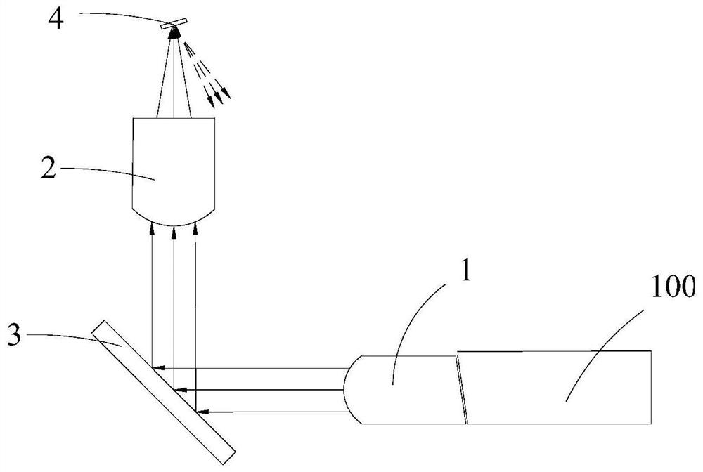
[0047] A structure to improve return loss, such as Figure 4 As shown, it includes a first collimating lens 1, a filter glass 3, a second collimating lens 2 and a PD chip 4;

[0048] The first collimating lens 1 is used to convert incident light into collimated light;

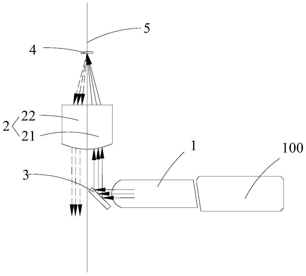
[0049] The axis of the second collimating lens 2 is perpendicular to the axis of the first collimating lens 1;

[0050] The second collimating lens 2 is provided with a virtual plane 5, the axis of the first collimating lens 1 is perpendicular to the virtual plane 5, and the axis of the second collimating lens 2 is located in the virtual plane 5;

[0051] The virtual plane 5 divides the second collimating lens 2 into a first partial lens 21 close to the first collimating lens 1 and a second partial lens 22 far from the first collimating lens 1;

[0052] The filter glass 3 is located on the side of the virtual plane 5 close to the first collimating lens 1, and is used to reflect the collimated light to the first partial l...

Embodiment 2

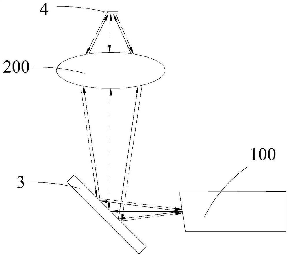
[0060] The difference between this embodiment and the first embodiment is that the filter glass 3 is located on the side of the virtual plane 5 away from the first collimating lens 1 and is used to reflect the collimated light to the second partial lens 22. Its structure and light path are as Figure 4 As shown, this structure is used for single-fiber bidirectional optical components.

Embodiment 3

[0062] This embodiment is different from Embodiment 1 in that the filter glass 3 includes a first filter glass 31 and a second filter glass 32. The first filter glass 31 is a 13° filter glass, and the second filter glass 32 is a +32° filter glass.

[0063] Such as Figure 5 As shown, the first filter glass 31 is located outside the optical path of the second collimating lens 2, that is, the first filter glass is not on the optical path of incident light and reflected light. The second filter glass 32 is located on the side of the virtual plane 5 close to the first collimating lens 1; the light of the optical fiber is converted into collimated light through the first collimating lens 1, and then reflected to the second through the first filter glass 31 The filter glass 32 is then reflected to the first partial lens 21 and reaches the photosensitive surface 4. The reflected light from the photosensitive surface 4 passes through the second partial lens 22 of the second collimating l...


PUM


Abstract

The invention relates to the field of optical communication, in particular to a structure for improving return loss, which comprises a first collimating lens, a filter, a second collimating lens and aPD chip. The first collimating lens is used for converting incident light into collimated light. The axis of the second collimating lens is perpendicular to the axis of the first collimating lens. The second collimating lens is provided with a virtual plane, and the virtual plane divides the second collimating lens into a first part of lens close to the first collimating lens and a second part oflens far away from the first collimating lens. The filter is located on the side, close to the first collimating lens, of the virtual plane and used for reflecting collimated light to the first partof lens, the PD chip is located behind the second collimating lens, and the photosensitive surface of the PD chip faces a lens assembly and is parallel to the axis of the first collimating lens. Separation of incident light and reflected light of the photosensitive surface is achieved, and meanwhile the requirements for responsivity, reliability and production efficiency are met.

Description

Technical field [0001] The present invention relates to the field of optical communication, in particular to a structure for improving return loss. Background technique [0002] Optical modules are widely used in wireless equipment and transmission equipment to provide fronthaul, midhaul, and backhaul, as well as optical network connection interfaces inside data centers. At present, as the fifth-generation mobile communication (5G) technology gradually enters the era of commercialization, the demand for optical modules in the future will further increase. As an important part of optical modules, optical devices must also meet the technical requirements of optical modules that can be applied in different scenarios. [0003] Return loss is an important parameter describing the performance of an optical device. It refers to that when an optical signal encounters an optical component during transmission within an optical device, part of the optical signal is reflected back to the tran...

Claims


Application Information

Patent Timeline
Patent Type & Authority Applications(China)
IPC IPC(8): G02B6/42
CPCG02B6/4204G02B6/4206G02B6/4214G02B6/4215
Inventor 马朝阳喻洋刘晓军赵银春
Owner 成都新易盛通信技术股份有限公司
Why Eureka
Try Eureka