Wafer bearing device and exposure equipment

A wafer carrying and wafer stage technology, applied in microlithography exposure equipment, optomechanical equipment, photolithography process exposure devices, etc., can solve the problem of wafer flatness decline, semiconductor device yield reduction, and wafer stage flatness reduction. and other problems, to achieve the effect of increasing available working time, improving semiconductor yield, and reducing cleaning time

Pending Publication Date: 2020-09-11
CHANGXIN MEMORY TECH INC
View PDF0 Cites 5 Cited by
  • Summary
  • Abstract
  • Description
  • Claims
  • Application Information

AI Technical Summary

Problems solved by technology

The wafer table and the mirror block cannot be absolutely attracted, so particles such as dust are easy to accumulate in the gap between the two, resulting in a decrease in the flatness of the wafer table, which in turn leads to the flatness of the wafer placed on the wafer table. decline, reducing the yield of semiconductor devices

Method used


Image

  • Wafer bearing device and exposure equipment
  • Wafer bearing device and exposure equipment
  • Wafer bearing device and exposure equipment

Examples


Embodiment Construction

[0058] Example embodiments will now be described more fully with reference to the accompanying drawings. Example embodiments may, however, be embodied in many forms and should not be construed as limited to the examples set forth herein; rather, these embodiments are provided so that this disclosure will be thorough and complete, and will fully convey the concept of example embodiments to those skilled in the art. The described features, structures, or characteristics may be combined in any suitable manner in one or more embodiments. In the following description, numerous specific details are provided in order to give a thorough understanding of embodiments of the present disclosure.

[0059] In the drawings, the thicknesses of regions and layers may be exaggerated for clarity. The same reference numerals in the drawings denote the same or similar structures, and thus their detailed descriptions will be omitted.

[0060] When a structure is "on" another structure, it may me...


PUM

PropertyMeasurementUnit
diameteraaaaaaaaaa

Abstract

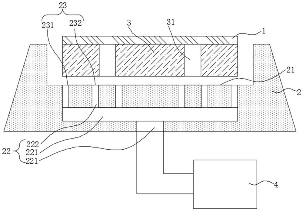
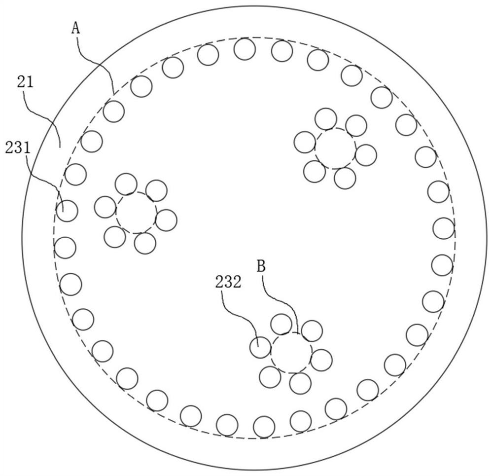
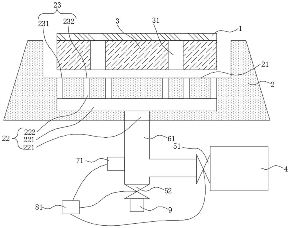
The invention provides a wafer bearing device and exposure equipment, and belongs to the technical field of photoetching equipment. The wafer bearing device comprises a reflecting mirror block, a wafer table and a negative pressure assembly, wherein the reflector block is provided with a bearing surface and a cleaning channel. The bearing surface is provided with a cleaning opening, and the cleaning opening is communicated with the cleaning channel. The wafer table is arranged on the bearing surface and is provided with a support pin hole. The negative pressure assembly is connected with the cleaning channel and used for providing negative pressure for the cleaning opening. According to the wafer bearing device and the exposure equipment, the flatness of the wafer table can be improved, and the yield of semiconductor devices is improved.

Description

technical field [0001] The present disclosure relates to the technical field of photolithography equipment, in particular to a wafer carrying device and exposure equipment. Background technique [0002] During the semiconductor manufacturing process, a wafer needs to be fixed on a wafer carrier. [0003] The wafer carrying device includes a wafer table for carrying wafers and a mirror block for carrying the wafer table, and the wafer table is fixed on the mirror block by a plurality of fixing pieces. The wafer table and the mirror block cannot be absolutely attracted, so particles such as dust are easy to accumulate in the gap between the two, resulting in a decrease in the flatness of the wafer table, which in turn leads to the flatness of the wafer placed on the wafer table. decline, reducing the yield of semiconductor devices. [0004] The above information disclosed in this Background section is only for enhancement of understanding of the background of the disclosure ...

Claims


Application Information

Patent Timeline
Patent Type & Authority Applications(China)
IPC IPC(8): H01L21/683H01L21/687G03F7/20
CPCG03F7/70716G03F7/70925H01L21/6838H01L21/68714
Inventor 周冬
Owner CHANGXIN MEMORY TECH INC
Why Eureka
Try Eureka