Power distribution box waterproof structure

A technology of power distribution box and waterproof structure, which is applied in the substation/distribution device casing, electrical components, substation/switch layout details, etc., can solve the problem of the air humidity inside the box rising with the external environment, and achieve a good dehumidification effect. , avoid circuit short circuit, improve the effect of dehumidification efficiency

Pending Publication Date: 2020-09-11
江苏锡沂水务有限公司
View PDF0 Cites 2 Cited by
  • Summary
  • Abstract
  • Description
  • Claims
  • Application Information

AI Technical Summary

Problems solved by technology

[0005] The purpose of the present invention is to provide a waterproof structure for power distribution boxes, which solves the problem in the background technology that after the distribution box is used in a high-humidity environment for a long time, the air humidity inside the box will still increase with the external environment

Method used


Image

  • Power distribution box waterproof structure
  • Power distribution box waterproof structure
  • Power distribution box waterproof structure

Examples


Embodiment 1

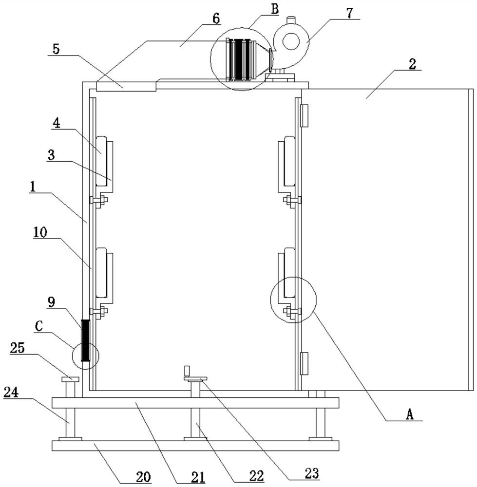
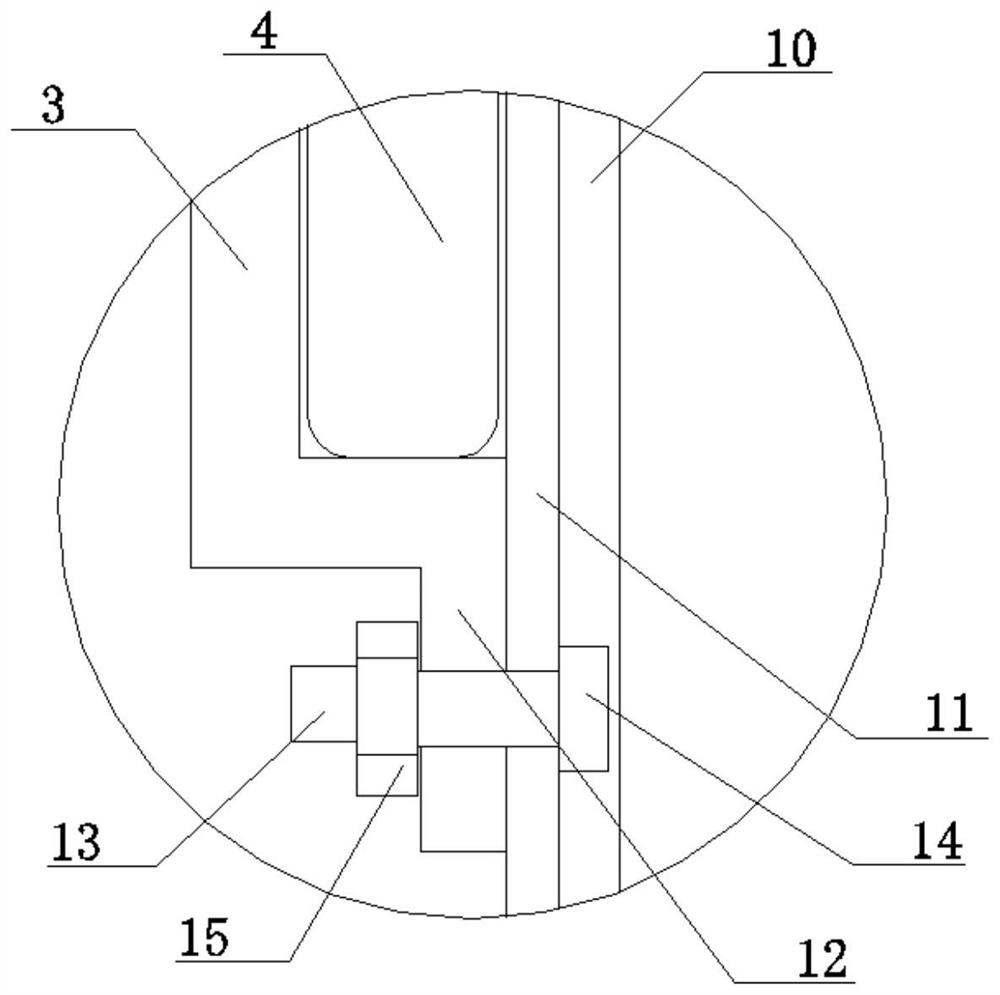
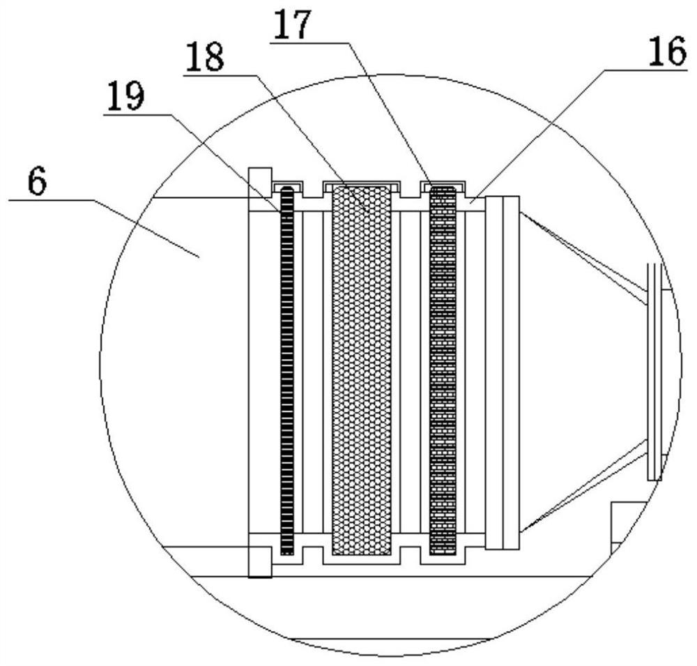
[0040] A waterproof structure for a power distribution box, comprising a box body 1, a box door 2 is hinged on the box body 1, a plurality of desiccant storage tanks 3 are movably connected to the inner wall surfaces on both sides of the box body 1, and the desiccant storage tanks 3 are A bagged desiccant 4 is provided, and the upper end of the box body 1 is provided with an air inlet 5, and the air inlet 5 is connected to a fan 7 through an air duct 6, and the fan 7 is fixedly connected to the top of the box body 1, and between the fan 7 and the air duct 6 It is also connected with a filter drying assembly, the lower part of the side wall of the box body 1 is provided with an air outlet 9, and the lower end of the box body 1 is also provided with a height adjustment assembly; the height adjustment assembly includes a base 20 and a movable seat 21. The sides are all rotatably connected with a screw mandrel 22, and the screw mandrel 22 is threadedly connected to the movable seat...

specific Embodiment approach

[0046] 1. Place the cabinet 1 at the designated position of the place to be installed, and turn the handle 23 according to the dry humidity of the ground of the place to be installed, and the handle 23 drives the screw rod 22 to rotate, and the screw rod 22 drives the movable seat 21 to rise to a suitable height;

[0047] 2. Open the box door 2, and place the bagged desiccant 4 in each desiccant storage tank 3;

[0048] 3. Install power distribution equipment in the box;

[0049] 4. According to the setting position of the power distribution equipment, loosen the fastening bolt 15, slide the desiccant storage tank 3 to a position close to the power distribution equipment, and re-tighten the fastening bolt 15 to fix the desiccant storage tank 3;

[0050] 5. Close the box door 2, start the fan 7, and the fan 7 will filter and dry the external air through the primary filter layer 17, the drying layer 18 and the fine filter layer 19, and then send it into the box body 1 through th...


PUM


Abstract

The invention discloses a power distribution box waterproof structure. The waterproof structure comprises a box body, a box door is hinged to the box body, the surfaces of the inner walls of the two sides of the box body are movably connected with a plurality of drying agent storage grooves, a bagged drying agent is arranged in the drying agent storage grooves, an air inlet is formed in the upperend of the box body and is connected with a draught fan through an air pipe, a filtering and drying assembly is further connected between the draught fan and the air pipe, an air outlet is formed in the lower portion of one side wall of the box body, and a height adjusting assembly is further arranged at the lower end of the box body. The drying agent storage grooves are formed in the box body tocontain the bagged drying agent, so moisture contained in air in the box body can be adsorbed at ordinary times, and the phenomenon of short circuit caused by too high air humidity in the box body canbe effectively avoided. The filtering and drying assembly is arranged to make air, sucked in by the draught fan, dried and filtered, the dried air enters the box body, the air in the box body can bereplaced, and when the air humidity in the box body is too high, the air humidity in the box body can be rapidly reduced, so the dehumidification efficiency is improved.

Description

technical field [0001] The invention relates to the technical field of power devices, in particular to a waterproof structure for a power distribution box. Background technique [0002] The distribution box is divided into power distribution box, lighting distribution box and metering box, and is the final equipment of the power distribution system. The distribution box is a general term for the motor control center. The distribution box is used in the occasions where the load is relatively scattered and there are few circuits; the motor control center is used in the occasions where the load is concentrated and there are many circuits. They distribute the electric energy of a certain circuit of the upper-level power distribution equipment to the nearest load. This level of equipment shall provide protection, monitoring and control of the load. [0003] The voltage in the distribution box is high. If water enters, it will leak electricity, which will cause danger, and will...

Claims


Application Information

Patent Timeline
Patent Type & Authority Applications(China)
IPC IPC(8): H02B1/28H02B1/56H02B1/50H02B1/46H02B1/48
CPCH02B1/28H02B1/46H02B1/48H02B1/505H02B1/565
Inventor 陈冬冬吴凌霄张瑜
Owner 江苏锡沂水务有限公司
Why Eureka
Try Eureka