Pressing rod device for spinal deformity correction operation

A spinal deformity and rod pressing technology, which is applied in the directions of surgery, medical science, internal bone synthesis, etc., to achieve the effect of reducing the difficulty of operation, convenient use and simplifying steps.

Pending Publication Date: 2020-09-15
NANJING CHILDRENS HOSPITAL
View PDF0 Cites 2 Cited by
  • Summary
  • Abstract
  • Description
  • Claims
  • Application Information

AI Technical Summary

Problems solved by technology

If the deformity is serious and the distance between the screw and the rod is still far away, you can only use the in-situ rod bender to change the shape of the pre-bent rod to adapt to the position of the screw, but this is at the cost of sacrificing part of the orthopedic effect

Method used


Image

  • Pressing rod device for spinal deformity correction operation
  • Pressing rod device for spinal deformity correction operation
  • Pressing rod device for spinal deformity correction operation

Examples


Embodiment 1

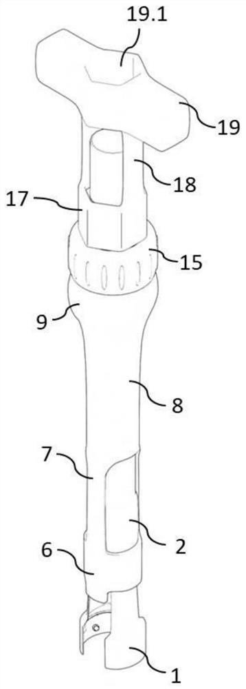
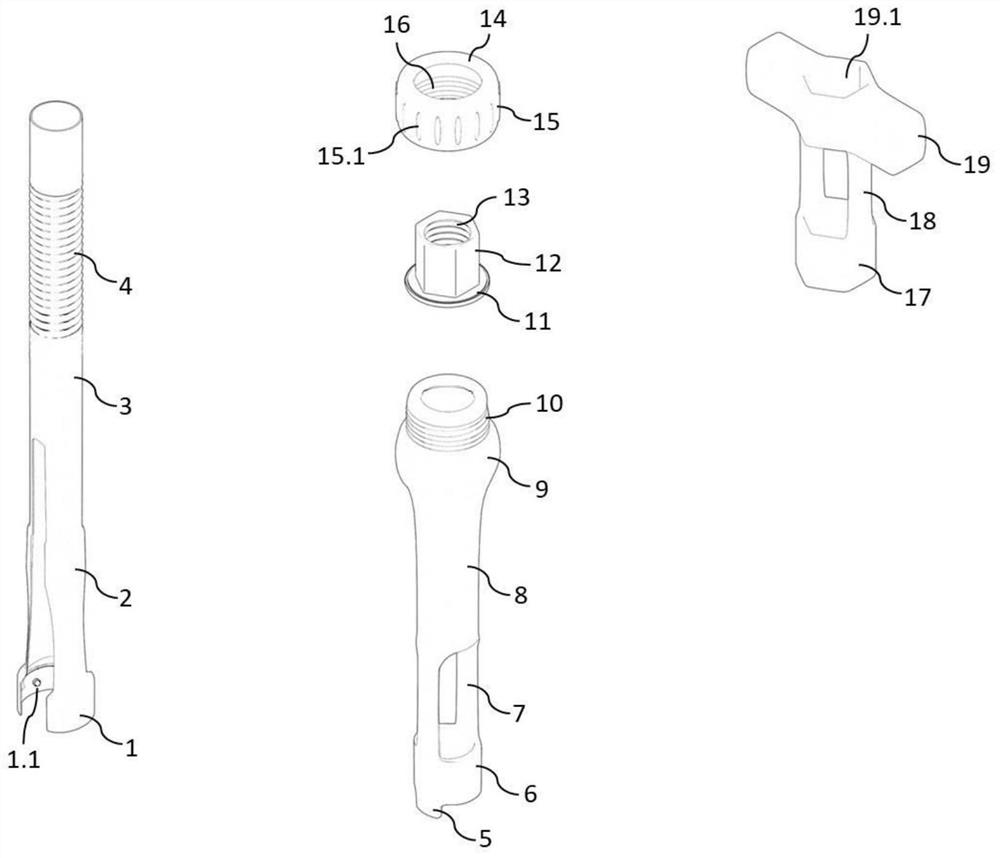
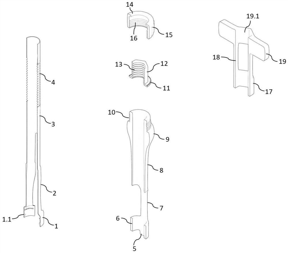
[0026] Embodiment 1: see Figure 1-Figure 4 , a compression rod device used for spinal deformity correction surgery, the compression rod device is composed of an inner tube, an outer tube, a rotating inner nut, a fixed outer nut and a matching T-shaped adjustment wrench. When in use, the inner tube, outer tube, rotating inner nut, and fixed outer nut are combined to form the main body of the pressing rod device, and then adjusted by the matching T-type wrench. In this scheme, if Figure 1-Figure 4 As shown, the inner tube includes a fixed claw 1, a lower bifurcated section 2, an inner tube body 3 and an upper external thread area 4, the fixed claw 1 is located below the lower bifurcated section 2, and the inner walls on both sides of the fixed claw have circles. Shaped protrusions 1.1. When in use, the protrusion is combined with the circular groove on the outer wall of the screw tail to play a fixed role. The fixed claws 1 on both sides extend upward to form the lower bifur...

Embodiment 2

[0032] Example 2: see Figure 1-Figure 4 , when the rod pressing device is assembled, the rotating inner nut is first placed on the top of the outer tube, the upper snap ring 14 of the fixed outer nut is pressed against the lower snap ring 11 of the rotating inner nut, and then the inner thread 16 of the fixed outer nut is connected with the The outer thread 10 on the top of the outer pipe is combined by rotation, and the outer pipe, the rotating inner nut and the fixed outer nut are combined into a whole. Then the inner pipe is inserted upwards from the lower end of the outer pipe, and then the outer thread 4 on the upper part of the inner pipe is combined with the inner thread 13 of the rotating inner nut to complete the assembly of the main body of the pressing rod device. During use, the fixed ring 17 of the T-type wrench is sleeved on the rotating inner nut body. Since the two are matching hexagonal appearance, the inner nut can be turned and rotated by twisting a T-type...


PUM


Abstract

The invention relates to a pressing rod device for spinal deformity correction surgery. The pressing rod device is composed of an inner pipe, an outer pipe, a rotary inner nut, a fixed outer nut and amatched T-shaped adjusting wrench; the inner pipe is composed of a fixed claw, a lower fork section, an inner pipe body and an upper external thread area; the outer pipe is composed of a pressing rodprotrusion, a restraining ring, a lower hollowed-out section, an outer pipe body, an upper protruding section and an upper outer thread area; the rotary inner nut is composed of a lower clamping ring, an inner nut body and an inner thread area; the fixing outer nut is composed of an upper clamping ring, an outer nut body and an inner thread area; and the T-shaped adjusting wrench is composed of afixing ring, a hollowed-out connecting section and a transverse handle. According to the device, the inner fixing rod and the screw can be combined more conveniently in a spinal deformity correctionoperation, simplicity and convenience of rod mounting operation are improved, the operation time is effectively shortened, and operation safety of a patient is improved.

Description

technical field [0001] The invention relates to a rod pressing device, in particular to a device for assisting rod loading during spinal deformity correction surgery, and belongs to the technical field of medical devices. Background technique [0002] Scoliosis is a common skeletal system disease in adolescents and children. According to the standards of the International Scoliosis Research Society (SRS), a scoliosis angle above 45°-50° meets the standard for orthopedic surgery. In the process of spinal orthopedic surgery, after completing the steps of pedicle screw placement and spinal osteotomy, it is necessary to fix the pre-bent orthopedic rod and the tail of the screw, and then perform derotation, distraction, tightening, and in-situ bending of the rod. The operation completes spinal correction. The process of fixing the orthopedic rod with pedicle screws of all spinal segments is called roding, and this step is very critical in the whole spinal orthopedic surgery. B...

Claims


Application Information

Patent Timeline
Patent Type & Authority Applications(China)
IPC IPC(8): A61B17/70
CPCA61B17/7002A61B17/7064A61B17/7074A61B17/7083A61B2017/564
Inventor 汪飞唐俊锋
Owner NANJING CHILDRENS HOSPITAL
Why Eureka
Try Eureka