Thread assembly used for setting lag screw state in intramedullary nail system and intramedullary nail system comprising thread assembly
A threaded component and intramedullary nail technology, applied in the field of intramedullary nail systems, to achieve the effect of easy use and simple structure
- Summary
- Abstract
- Description
- Claims
- Application Information
AI Technical Summary
Problems solved by technology
Method used
Image
Examples
Embodiment 1
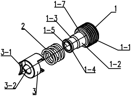
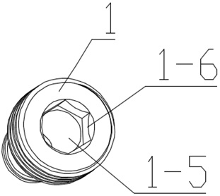
[0044] Example 1: Image 6 It is a schematic diagram of the use state of a threaded component used to set the state of a lag screw in an intramedullary nail system. The intramedullary nail system includes a driving part 1, a spring 2, a clamping part 3, a tail cap 4, a lag screw 5, a main nail 6, a locking nail 7 and a compression screw 8 in the threaded assembly composition.
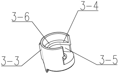
[0045] In a further embodiment, the thread assembly (Set Screw) involved in this invention is pre-installed in the central through hole 6 - 1 of the proximal end of the main nail 6 . The semicircular guide boss 3-3 on the side wall of the clamping part 3 is compatible with the guide groove 6-3 in the central through hole 6-1 of the main nail on the main nail 6 of the intramedullary nail. The clamping part 3 can move up and down in the central through hole 6-1 along the guide groove 6-3. The external thread 1-1 of the proximal part of the driving part is compatible with the internal thread 6-2 in the ...
Embodiment 2
[0047] Example 2: Image 6 It is a schematic view of the use state of a threaded assembly used to set the state of a lag screw in an intramedullary nail system. The intramedullary nail system includes a driving part 1, a spring 2, a clamping part 3, a Tail cap 4, a lag screw 5, a main intramedullary nail 6, a locking nail 7 and a compression thread 8.
[0048] In a further embodiment, the thread assembly (Set Screw) involved in this invention is pre-installed in the central through hole 6-1 of the proximal end of the main nail 6, and the semicircular guide protrusion on the side wall of the clamping part 3 The platform 3-3 is compatible with the guide groove 6-3 in the central through hole 6-1 on the main nail 6, and the clamping part 3 can move up and down along the guide groove 6-3. The external thread 1-1 at the proximal end of the driving part is compatible with the internal thread 6-2 in the central through hole 6-1 of the main nail. During the operation, the tool is in...
PUM
 Abstract
Description
Claims
Application Information
 - R&D
- Intellectual Property
- Life Sciences
- Materials
- Tech Scout
- Unparalleled Data Quality
- Higher Quality Content
- 60% Fewer Hallucinations
Browse by: Latest US Patents, China's latest patents, Technical Efficacy Thesaurus, Application Domain, Technology Topic, Popular Technical Reports.
© 2025 PatSnap. All rights reserved.Legal|Privacy policy|Modern Slavery Act Transparency Statement|Sitemap|About US| Contact US: help@patsnap.com


