Cleaning device for chromatographic bottle for chemical laboratory

A technology for chemical laboratories and cleaning devices, applied in chemical instruments and methods, cleaning hollow objects, cleaning methods and utensils, etc., can solve the problems of difficult cleaning of chromatographic bottles, low cleaning efficiency, etc., to improve cleaning effect and efficiency. , good cleaning effect

Inactive Publication Date: 2020-09-15
魏朵朵
View PDF0 Cites 6 Cited by
  • Summary
  • Abstract
  • Description
  • Claims
  • Application Information

AI Technical Summary

Problems solved by technology

[0005] The purpose of the present invention is to provide a cleaning device for chromatographic bottles with high efficiency and good cleaning effect in view of the problems that the chromatographic bottles are difficult to clean and the cleaning efficiency is low

Method used


Image

  • Cleaning device for chromatographic bottle for chemical laboratory
  • Cleaning device for chromatographic bottle for chemical laboratory
  • Cleaning device for chromatographic bottle for chemical laboratory

Examples


Embodiment 1

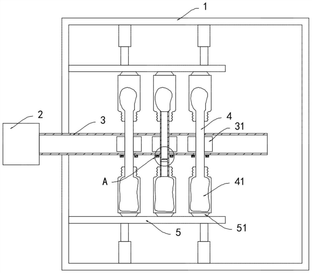
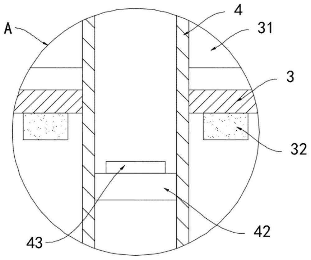
[0020] like Figure 1-3 As shown, a cleaning device for chromatographic bottles used in a chemical laboratory includes a cleaning tank 1 and a blower fan 2. A horizontal air pipe 3 is provided in the cleaning tank 1. One end of the air pipe 3 runs through the side wall of the cleaning tank 1 and connects with the blower fan 2. It is fixed and communicated. There are a plurality of rotating tubes 4 perpendicular to the axial direction running through the air pipe 3. The rotating pipes 4 are connected to the air pipe 3 in a sealed and rotating manner. The air pipe 3 is provided with a plurality of windward plates 31, which are installed in a circular array. On the side wall of the rotating tube 4, both ends of the rotating tube 4 are fixedly connected with a telescopic air bag 41, and the outer part of the telescopic air bag 41 is fixedly embedded with bristles. scrape off.

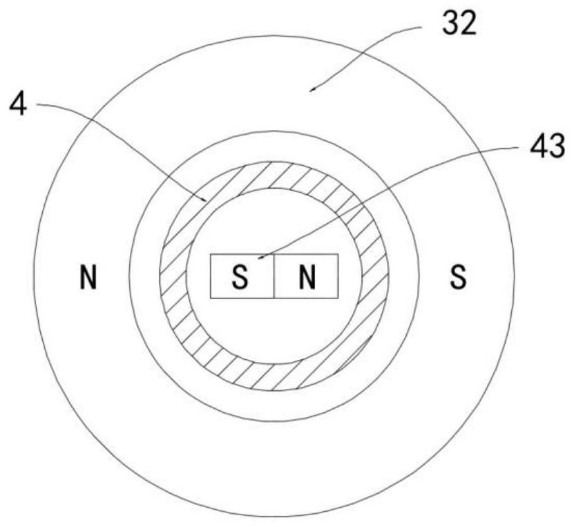
[0021] Piston block 42 is sealed and slidably connected in rotating tube 4, and bar magnet 43 is fixedl...

Embodiment 2

[0024] like Figure 4-5 As shown, the difference between the present embodiment and Embodiment 1 is that the impeller 6 is sleeved on the outside of the air pipe 3, and the blades of the impeller 6 are provided with exhaust passages 61 communicating with the air pipe 3, and a plurality of exhaust passages 61 are arranged along the The impeller 6 is radially arranged, and a plurality of exhaust holes 62 are opened on the side wall of the exhaust passage 61, and the opening directions of the plurality of exhaust holes 62 are consistent.

[0025] In this embodiment, the air in the air pipe 3 enters the exhaust channel 61 and is discharged through a plurality of exhaust holes 62. When the air flow is discharged, a reaction force along the axis direction of the exhaust holes 62 is provided to the impeller 6 to drive the impeller 6. Rotate to promote the flow of the cleaning liquid in the cleaning tank 1, avoiding the sewage carrying the stains to linger around the chromatographic b...


PUM


Abstract

The invention belongs to the technical field of chemical laboratory appliance cleaning, and particularly relates to a cleaning device for a chromatographic bottle for a chemical laboratory. The devicecomprises a cleaning tank and a fan, wherein a horizontally arranged air pipe is arranged in the cleaning tank, one end of the air pipe penetrates through the side wall of the cleaning tank and fixedly communicates with the fan, a plurality of rotating pipes perpendicular to an axis direction thereof are arranged in the air pipe in a penetrating mode, the rotating pipes are hermetically and rotatably connected with the air pipe, a plurality of windward plates are arranged in the air pipe, the plurality of windward plates are arranged on the side walls of the rotating pipes in an annular arraymode, stretchable air bags fixedly communicate to the two ends of the rotating pipes, piston blocks are hermetically and slidably connected in the rotating pipes, and strip-shaped magnets are fixedlyconnected to the side walls of the piston blocks. According to the device, the stretchable air bags are periodically expanded and contracted, air in the chromatographic bottle is squeezed out, cleaning water is repeatedly sucked into and discharged from the chromatographic bottle, solution stains in the chromatographic bottle are flushed and taken away by the cleaning water, the cleaning effect is good, and the efficiency is high.

Description

technical field [0001] The invention belongs to the technical field of cleaning of chemical laboratory utensils, in particular to a cleaning device for chromatographic bottles used in chemical laboratories. Background technique [0002] Chromatography is a commonly used instrument for chromatographic separation in chemical laboratories. It uses different partition coefficients of different substances in a system composed of stationary phase and mobile phase to separate components in complex mixtures. When the chromatograph is in use, It is necessary to use a chromatographic bottle with the same specification to contain the solution to be tested for detection. [0003] After the detection is completed, the chromatographic bottle needs to be cleaned. However, due to the small diameter of the chromatographic bottle, it is difficult for the cleaning water to enter the bottle due to the effect of surface tension, resulting in residual solution in the bottle, which affects the nex...

Claims


Application Information

Patent Timeline
Patent Type & Authority Applications(China)
IPC IPC(8): B08B9/36B08B9/20B08B13/00
CPCB08B9/20B08B9/36B08B13/00
Inventor 魏朵朵刘珍
Owner 魏朵朵
Why Eureka
Try Eureka