Round tube inner wall grinding device for mechanical manufacturing

A technology for machine manufacturing and round pipes, which is applied to the field of grinding devices for the inner wall of round pipes for machine manufacturing, can solve the problems of increased work strength, poor fit, inconvenient grinding work, etc., so as to reduce work strength, improve fit, and avoid jamming. Effect

Inactive Publication Date: 2020-09-15
青欣智能科技(烟台)有限公司
View PDF1 Cites 6 Cited by
  • Summary
  • Abstract
  • Description
  • Claims
  • Application Information

AI Technical Summary

Problems solved by technology

[0003] After searching, the Chinese patent publication number is the patent of CN206550766U, which discloses a kind of high-efficiency automatic grinding machine inside and outside the circular tube. The motor drives the grinding roller to grind the inner wall of the round tube, and at the same time, another lifting mechanism is used to move the grinding roller laterally, resulting in poor cooperation between multiple mechanisms, which not only consumes high energy, but also increases people's work. Working intensity; at the same time, in the process of grinding the inner wall of the round tube by the grinding roller, due to thermal expansion and contraction, the grinding roller will be stuck on the inner wall of the round tube and cannot be pulled out, which will bring great inconvenience to people's grinding work

Method used


Image

  • Round tube inner wall grinding device for mechanical manufacturing
  • Round tube inner wall grinding device for mechanical manufacturing
  • Round tube inner wall grinding device for mechanical manufacturing

Examples


Embodiment 1

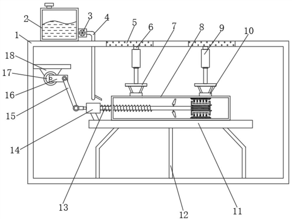
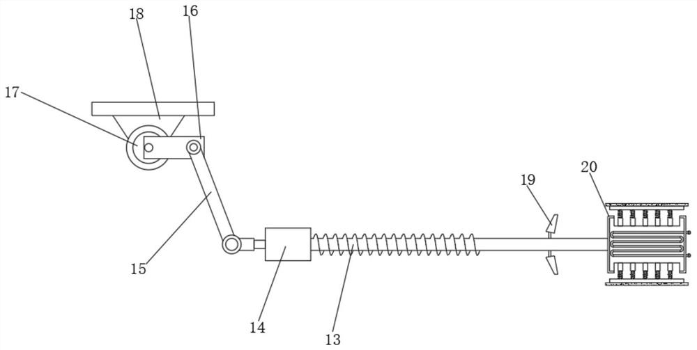
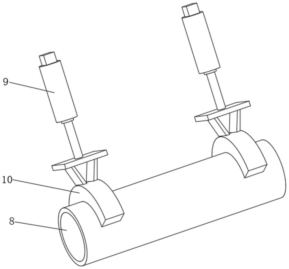
[0028] refer to Figure 1-4 , a circular tube inner wall grinding device for mechanical manufacturing, comprising a box body 1, the bottom inner wall of the box body 1 is connected with a support leg 12 by bolts, and the top outer wall of the support leg 12 is connected with a workbench 11 by bolts, and the workbench 11 A cylinder 8 is placed on the top outer wall of the box body 1, and a support plate is connected to one side of the inner wall of the box body 1 by bolts, and the bottom outer wall of the support plate is connected to a fixing seat 18 by bolts, and the bottom outer wall of the fixing seat 18 is connected to a motor 17 by bolts, And the output shaft outer wall of motor 17 is socketed with crank 16, and one side outer wall of crank 16 is connected with connecting rod 15 by rotating shaft, and one end outer wall of connecting rod 15 is connected with fixed rod 27 by rotating shaft, and one side outer wall of fixed rod 27 rotates Connected with threaded rod 13, one...

Embodiment 2

[0032] refer to Figure 5, a circular pipe inner wall grinding device for mechanical manufacturing. Compared with Embodiment 1, the inner walls of both sides of the fixed column 20 are provided with air inlet slots 28, and the cross section of the air inlet slots 28 is funnel-shaped. A cooling channel 29 is opened inside the column 20 , and the cooling channel 29 is divided into equidistant broken lines, and one end of the air inlet slot 28 is connected to the cooling channel 29 .

[0033] Working principle: When people need to polish the inner wall of the cylinder 8, they can place it on the workbench 11, and then people start the electric push rod 9, and the electric push rod 9 drives the clamping ring 10 down to tighten the cylinder 8. When the cylinder body 8 is fixed by the clamping ring 10, people start the motor 17, and the motor 17 drives the crank 16 to rotate, and the crank 16 is connected to the connecting rod 15 through a hinge, so that the connecting rod 15 can dr...


PUM


Abstract

The invention discloses a round tube inner wall grinding device for mechanical manufacturing. The device comprises a box body, supporting legs are mounted on the inner wall of the bottom of the box body, a worktable is arranged on the outer walls of the tops of the supporting legs, a cylinder body is arranged on the outer wall of the top of the worktable, a supporting plate is arranged on the inner wall of one side of the box body, a fixed base is arranged on the outer wall of the bottom of the supporting plate, a motor is arranged on the outer wall of the bottom of the fixed base, the outer wall of an output shaft of the motor is sleeved with a crank, the outer wall of one side of the crank is connected with a connecting rod through a rotating shaft, a person can start the motor, the motor drives the crank to rotate, meanwhile, the crank is connected with the connecting rod through a hinge, therefore, the connecting rod can drive a thread rod to transversely move, the thread rod transversely moves and can make contact with the inner wall of a thread sleeve, the thread rod can drive a grinding ring to grind the inner wall of a cylinder body, the cooperation degree between the structures can be improved, and the work intensity of persons can be reduced.

Description

technical field [0001] The invention relates to the technical field of circular tube inner wall grinding, in particular to a circular tube inner wall grinding device for mechanical manufacturing. Background technique [0002] Grinding refers to the use of mechanical, chemical or electrochemical action to reduce the surface roughness of the workpiece to obtain a bright and smooth surface. It is a modification process on the surface of the polished workpiece by using grinding tools and abrasive particles or other grinding media. Grinding cannot improve the dimensional accuracy or geometric shape accuracy of the workpiece, but for the purpose of obtaining a polished smooth surface or a polished mirror luster. Sometimes it is also used for Removes shine. Usually a grinding wheel is used as a grinding tool. The grinding wheel is generally made of multiple layers of grinding canvas, grinding felt or leather, and the two sides are clamped by metal discs. [0003] After searching...

Claims


Application Information

Patent Timeline
Patent Type & Authority Applications(China)
IPC IPC(8): B24B5/40B24B55/02B24B41/02B24B47/04B24B41/06B24B55/06
CPCB24B5/40B24B41/02B24B41/067B24B47/04B24B55/02B24B55/06
Inventor 史青青
Owner 青欣智能科技(烟台)有限公司
Why Eureka
Try Eureka