Cloth dyeing device with uniform dyeing for textile processing
A dyeing device and cloth technology, applied in textile processing machine accessories, textile material processing, textile material processing equipment configuration, etc., can solve the problems of reducing cloth dyeing quality, uneven coloring, etc., to increase the mixing effect and facilitate stirring Effect
- Summary
- Abstract
- Description
- Claims
- Application Information
AI Technical Summary
Problems solved by technology
Method used
Image

Examples
Embodiment 1
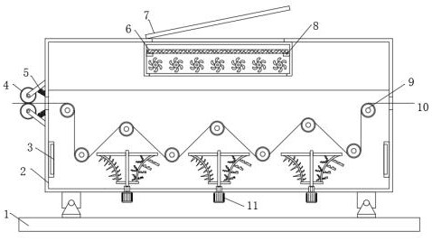
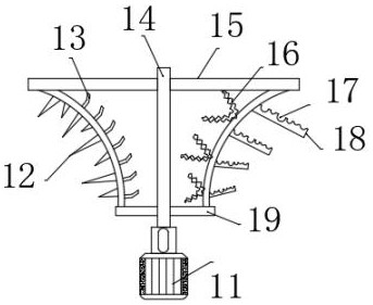
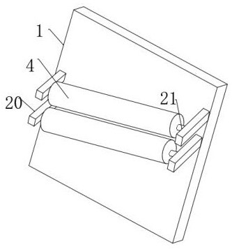
[0030] refer to Figure 1-4 , a cloth dyeing device for uniform dyeing in textile processing, comprising a bottom plate 1, a dyeing box 2 fixed on the top outer wall of the bottom plate 1 by screws, and an equidistantly distributed motor 11 fixed on the inner wall of the bottom inner wall of the dyeing box 2 by screws, the motor The output shaft of 11 is connected with rotating rod 14 by coupling, and one side outer wall of rotating rod 14 is fixed with first cross bar 19 and second cross bar 15 by screw, the first cross bar 19 and the second cross bar 15 One side of the outer wall is welded with a fixed rod, the fixed rod is an arc structure, the length of the first cross bar 19 and the second cross bar 15 are different, and the first cross bar 19, the second cross bar 15 and the fixed rod generally present a horn-shaped structure , the two sides of the outer wall of one of the fixed rods are respectively provided with equidistantly distributed conical stirring rods 12 and th...
Embodiment 2
[0038] refer to Figure 5 , a cloth dyeing device for uniform dyeing in textile processing. Compared with Embodiment 1, this embodiment also includes a second spring 25 welded to both sides of the top outer wall of the second cross bar 15, and the top outer walls of the second spring 25 are all set There is an inclined stirring rod 26, and two inclined stirring rods 26 are hinged to each other.
[0039] Connect the device to the power supply, open the cover body 7 and add the dye to the dyeing box 2, the dye solution is filtered through the filter plate 6, the dye can be stirred to a certain extent by the rotating rod 23 and the rubber stirring rod 26, and the cloth is processed When coloring, turn on the motor 11, and the motor 11 drives the rotating rod 14 to rotate in the middle. The first cross bar 15, the second cross bar 15 and the fixed rod generally present a horn-shaped structure. The horn-shaped structure can enlarge the vortex generated during stirring and increase ...
PUM
 Abstract
Description
Claims
Application Information