Cable-crossing crane of suspension bridge as well as application and using method of cable-crossing crane
A suspension bridge and span cable technology, applied in suspension bridges, cable cranes, bridges, etc., can solve the problems of large deformation of stiffening beams and very high requirements for hoisting capacity of hoisting units
- Summary
- Abstract
- Description
- Claims
- Application Information
AI Technical Summary
Problems solved by technology
Method used
Image
Examples
Embodiment 1
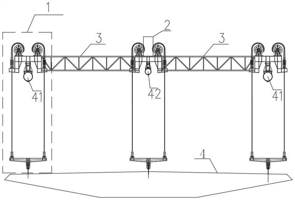
[0024] like figure 1 As shown, a cable-span crane for a suspension bridge includes a hoisting unit 1, a hydraulic control unit 2, and a beam 3. The number of hoisting units 1 is 3 sets, and the 3 sets of hoisting units 1 are sequentially connected through the beam 3 from left to right. The control unit 2 is connected with the lifting unit 1 in the middle. The cable-span crane of the suspension bridge is provided with a set of lifting units 1 at the left, middle and right positions of the three main cables (ie, the side main cable 41 and the middle main cable 42), and the middle lifting unit 1 shares the lifting units on both sides. 1, and the deformation of the stiffening beam 4 is also within the controllable range. This structure has high practical significance and research value. The suspension bridge laid a certain foundation for construction.
Embodiment 2
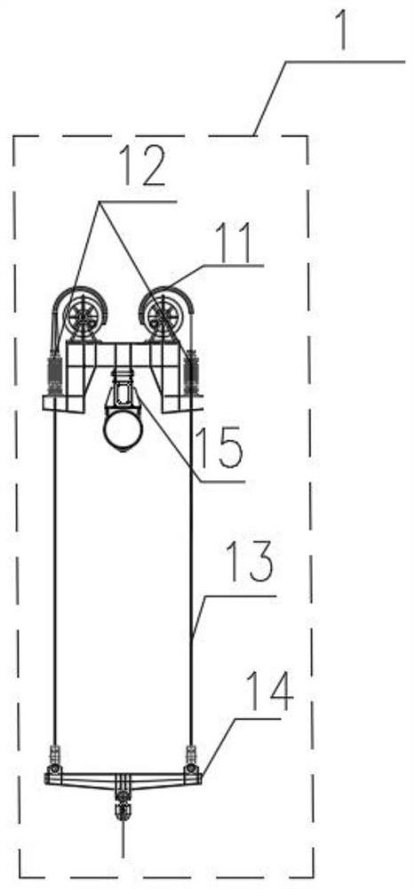
[0026] like figure 2 As shown, on the basis of Embodiment 1, the hoisting unit 1 includes 2 hoisting units, a sling 14 and a support leg 15, the 2 hoisting units are symmetrically connected left and right, and the middle lower part of the 2 hoisting units is connected to the support leg 15, The bottoms of the two hoisting units are connected to the spreader 14. The structure is simple, stable and balanced in force.
[0027] Each lifting unit includes a wire reel 11 , a lifting device 12 and a wire rope 13 , the wire reel 11 is wound with a wire rope 13 , and one end of the wire rope 13 passes through the lifting device 12 to connect to a hanger 14 . The working principle of the hoisting unit 1 is as follows: the hoisting unit is supported on the main cable through the supporting legs 15. When the stiffening beam 4 needs to be hoisted, the steel wire drum 11 lowers the steel wire rope 13, and the sling 14 moves to the position of the stiffening beam 4, and the sling 14 and th...
Embodiment 3
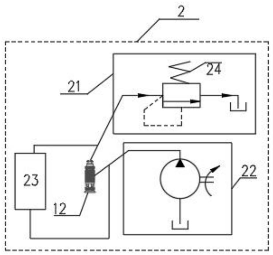
[0029] like image 3 As shown, on the basis of Embodiment 2, the hydraulic control unit 2 includes an oil discharge valve 21, an oil supply pump 22, a signal collector 23, and a safety switch 24, and the lifting device 12 is connected to the signal collector 23 and the oil discharge valve respectively. 21 and the oil supply pump 22, the oil unloading valve 21 is connected with the safety switch 24. Three sets of hoisting units 1 are connected as a whole by a beam 3. When hoisting the stiffening girder 4 of the suspension bridge, the above-mentioned spanning crane is supported on the three main cables (side main cable 41 and middle main cable 42). When the above three sets of hoisting units are stressed, in order to prevent the deformation of the 3 mid-span of the beam from being too large (the deformation limit can be obtained through relevant specifications) and at the same time to share the force of the hoisting units on the main cable on the side (this can be done in a cert...
PUM
 Abstract
Description
Claims
Application Information
 - R&D
- Intellectual Property
- Life Sciences
- Materials
- Tech Scout
- Unparalleled Data Quality
- Higher Quality Content
- 60% Fewer Hallucinations
Browse by: Latest US Patents, China's latest patents, Technical Efficacy Thesaurus, Application Domain, Technology Topic, Popular Technical Reports.
© 2025 PatSnap. All rights reserved.Legal|Privacy policy|Modern Slavery Act Transparency Statement|Sitemap|About US| Contact US: help@patsnap.com


