Engine
An engine and mover technology, which is applied in the direction of machines/engines, free piston engines, mechanical equipment, etc., can solve the problems of high instantaneous power requirements of motors, high noise, and large volume, and achieve good energy saving and environmental protection. high cost effect
- Summary
- Abstract
- Description
- Claims
- Application Information
AI Technical Summary
Problems solved by technology
Method used
Image

Examples
Embodiment 1
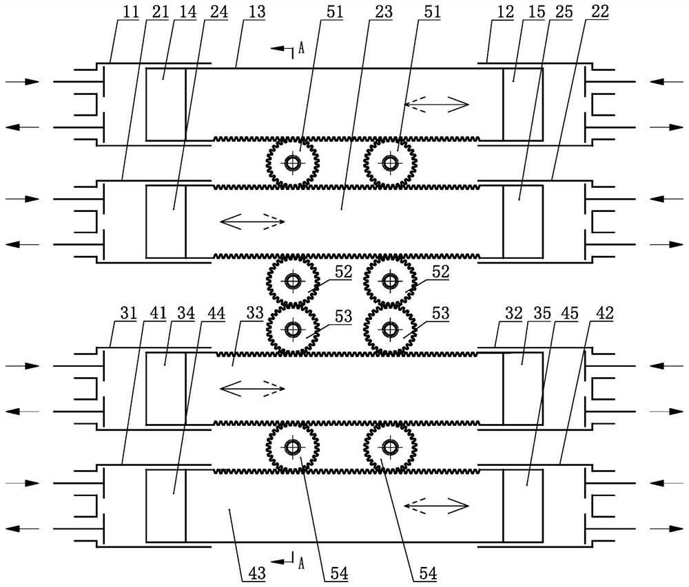
[0037] an engine such as figure 1 shown, including cylinder A 1 11. Cylinder A 2 12. Cylinder B 1 21. Cylinder B 2 22. Cylinder C 1 31. Cylinder C 2 32. Cylinder D 1 41. Cylinder D 2 42. Reciprocating mover A13, reciprocating mover B 23, reciprocating mover C 33, reciprocating mover D 43, transmission gear AB 51, transmission gear B 1 52. Transmission gear B 2 53 and transmission gear CD 54, the piston A is set on the reciprocating mover A13 1 14 and Piston A 2 15. Set the piston B on the reciprocating mover B 23 1 24 and Piston B 2 25. Set the piston C on the reciprocating mover C 33 1 34 and Piston C 2 35. Set the piston D on the reciprocating mover D 43 1 44 and Piston D 2 45, the piston A 1 14 set on the cylinder A 1 11. Inside, the piston A 2 15 set on the cylinder A 2 12. Inside, the piston B 1 24 set on the cylinder B 1 21, the piston B 2 25 set on the cylinder B 2 22, the piston C 1 34 set on the cylinder C 1 31, the ...
Embodiment 2
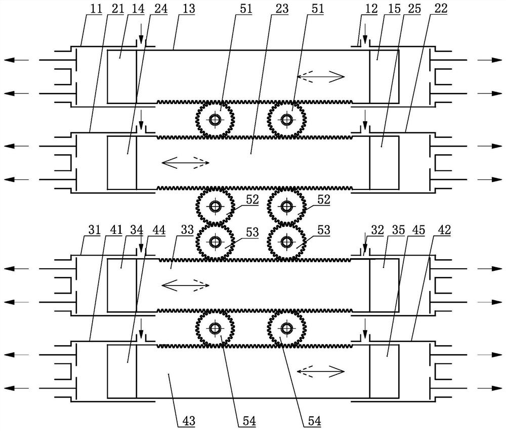
[0039] an engine such as figure 2 shown, including cylinder A 1 11. Cylinder A 2 12. Cylinder B 1 21. Cylinder B 2 22. Cylinder C 1 31. Cylinder C 2 32. Cylinder D 1 41. Cylinder D 2 42. Reciprocating mover A13, reciprocating mover B 23, reciprocating mover C 33, reciprocating mover D 43, transmission gear AB 51, transmission gear B 1 52. Transmission gear B 2 53 and transmission gear CD 54, the piston A is set on the reciprocating mover A13 1 14 and Piston A 2 15. Set the piston B on the reciprocating mover B 23 1 24 and Piston B 2 25. Set the piston C on the reciprocating mover C 33 1 34 and Piston C 2 35. Set the piston D on the reciprocating mover D 43 1 44 and Piston D 2 45, the piston A 1 14 set on the cylinder A 1 11. Inside, the piston A 2 15 set on the cylinder A 2 12. Inside, the piston B 1 24 set on the cylinder B 1 21, the piston B 2 25 set on the cylinder B 2 22, the piston C 1 34 set on the cylinder C 1 31, the...
Embodiment 3
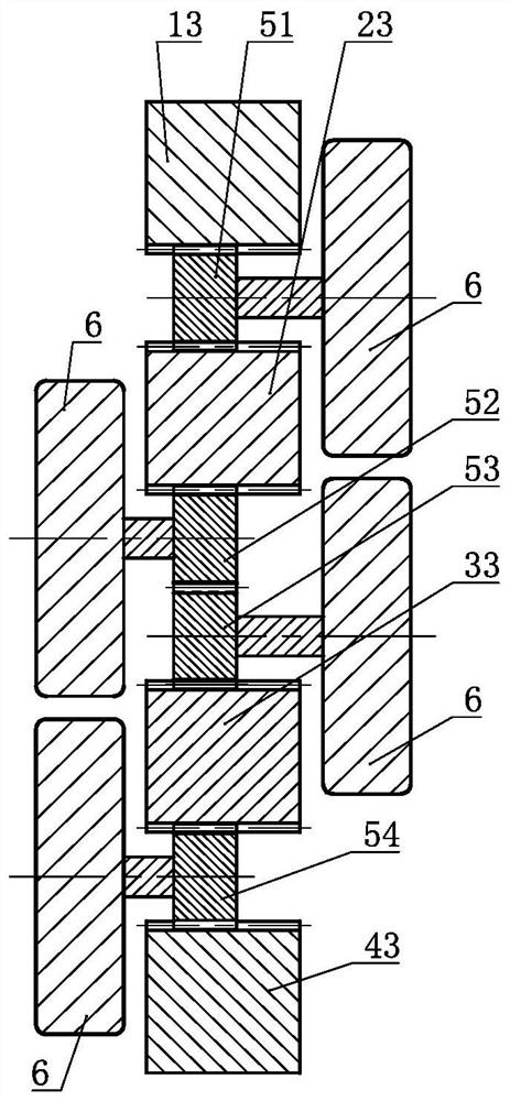
[0047] an engine such as image 3 As shown, the difference between it and Embodiment 1 is: the transmission gear AB 51, the transmission gear B 1 52. The transmission gear B 2 53 and the transmission gear CD 54 are set in linkage with a mass of inertia 6 respectively.
[0048] As a changeable implementation mode, Embodiment 3 of the present invention can also selectively choose to make the transmission gear AB51, the transmission gear B 1 52. The transmission gear B 2 53 and one, two or three of the transmission gear CD 54 are set in linkage with the mass of inertia 6 .
[0049] As a transformable embodiment, Embodiment 2 of the present invention and its transformable embodiment and the transformable embodiment of Embodiment 1 can further selectively select the transmission gear AB 51, the transmission gear B 1 52. The transmission gear B 2 53 and at least one of the transmission gear CD 54 is set in linkage with the mass of inertia 6 .
[0050] All the aforementio...
PUM
 Abstract
Description
Claims
Application Information
 - Generate Ideas
- Intellectual Property
- Life Sciences
- Materials
- Tech Scout
- Unparalleled Data Quality
- Higher Quality Content
- 60% Fewer Hallucinations
Browse by: Latest US Patents, China's latest patents, Technical Efficacy Thesaurus, Application Domain, Technology Topic, Popular Technical Reports.
© 2025 PatSnap. All rights reserved.Legal|Privacy policy|Modern Slavery Act Transparency Statement|Sitemap|About US| Contact US: help@patsnap.com