Methods and systems to control fuel scavenging in a split exhaust engine

A technology for engine cylinders and engines, applied in charging systems, engine components, combustion engines, etc., can solve problems such as knocking, knocking problems, and increasing engines.

Pending Publication Date: 2020-09-15
FORD GLOBAL TECH LLC
View PDF0 Cites 0 Cited by
  • Summary
  • Abstract
  • Description
  • Claims
  • Application Information

AI Technical Summary

Problems solved by technology

However, engine knock may occur due to increased combustion temperature
Knocking

Method used


Image

  • Methods and systems to control fuel scavenging in a split exhaust engine
  • Methods and systems to control fuel scavenging in a split exhaust engine
  • Methods and systems to control fuel scavenging in a split exhaust engine

Examples


Embodiment Construction

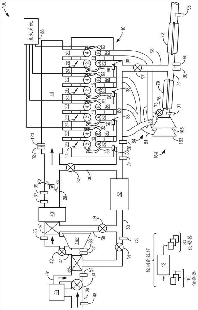
[0016] The following description relates to operating a split exhaust engine with blowing and exhaust gas recirculation (EGR) via a scavenging exhaust manifold to the intake and adjusting direct injection connected short-circuited via said scavenging manifold Systems and methods for an amount of fuel. Such as figure 1 As shown in , the split exhaust engine includes a first exhaust manifold (herein referred to as the blowdown manifold) coupled exclusively to the blown exhaust valve of each cylinder, and a A second exhaust manifold for scavenging the exhaust valves (referred to herein as a scavenging manifold). The scavenging manifold is coupled to the intake passage upstream of the turbocharger compressor via an EGR passage. In some embodiments, the split-exhaust engine system may include couplings such as figure 1 Additional channels between the scavenging manifold and the intake or exhaust channels shown in . Additionally, in some embodiments, split exhaust engine systems...


PUM


Abstract

Methods and systems are provided for adjusting amount of directly injected fuel scavenged via a second exhaust manifold of a split exhaust engine system. In one example, a method may include adjustinga start of injection of a fuel direct injection into an engine cylinder, the cylinder including a first exhaust valve coupled to a first exhaust manifold and a second exhaust valve coupled to a second exhaust manifold, the second exhaust manifold coupled to an intake of the engine, based on a closing timing of the second exhaust valve and dependent on an operating condition, and adjusting a position of a bypass valve of the second exhaust manifold based on the adjusted start of injection. In this way, the amount of scavenged fuel may be increased or decreased based on the operating condition.

Description

technical field [0001] The present description generally relates to systems and methods for engines having split exhaust systems. Background technique [0002] Engines may use boosting devices, such as turbochargers, to increase engine power density. However, engine knock may occur due to increased combustion temperatures. Knocking is especially problematic under boost conditions due to high charge temperatures. The inventors herein have recognized that a split exhaust system can reduce engine knock and increase engine efficiency, wherein a first exhaust manifold delivers exhaust to the turbine of a turbocharger in the exhaust port of the engine, and a second The exhaust manifold delivers exhaust gas recirculation (EGR) to the intake of the engine upstream of the compressor of the turbocharger. In such an engine system, each cylinder may include two intake valves and two exhaust valves, with a first set of cylinder exhaust valves (e.g., blown exhaust valves) being coupled...

Claims


Application Information

Patent Timeline
IPC IPC(8): F02D41/40F02D41/06F02D9/04F02D9/08F02D13/02F02D41/00F02M26/05F02M26/07F02M26/20F02M26/43F01N13/08F01N13/10
CPCF01N13/08F01N13/107F02D9/04F02D9/08F02D13/0249F02D41/0077F02D41/064F02D41/401F02M26/05F02M26/07F02M26/20F02M26/43F01N3/031F01N3/2006F01N3/2033F01N3/2892F01N2340/06F01N2430/06F01N2430/08F01N2430/10F01N2900/08F01N2900/1404F01N2900/1602F02D13/0257F02D13/0261F02D41/0007F02D41/0065F02D2013/0292F02D2041/389F02M26/09F02M26/14F02M26/22Y02T10/12Y02T10/40F02D41/0047F02D2200/10
Inventor 穆罕纳德·哈基姆阿什利·彼得·威斯丹尼尔·麦迪逊布拉德·波伊尔杜希扬·卡斯基延威廉·卡里·科尔约瑟夫·诺曼·乌雷
Owner FORD GLOBAL TECH LLC
Why Eureka
Try Eureka