
MIMO radar sparse array optimization method based on MODE algorithm

A technology of sparse array and optimization method, applied in the direction of reflection/re-radiation of radio waves, utilization of re-radiation, measurement devices, etc., can solve the difficulty of increasing system development, low imaging resolution, increasing system volume, weight and cost and other problems, to achieve the effect of easy programming, good function optimization performance, and simple structure

Inactive Publication Date: 2020-09-15
SHIJIAZHUANG TIEDAO UNIV +1
View PDF4 Cites 5 Cited by
  • Summary
  • Abstract
  • Description
  • Claims
  • Application Information

AI Technical Summary

Problems solved by technology

Generally speaking, the system imaging resolution achieved by the current system is still low. In order to achieve higher angular resolution, the method of further optimizing the radar sparse array and increasing the number of cascade modules can be adopted, but this will inevitably increase the volume of the system , weight and cost, but also increased the difficulty of system development

Method used


Image

  • MIMO radar sparse array optimization method based on MODE algorithm
  • MIMO radar sparse array optimization method based on MODE algorithm
  • MIMO radar sparse array optimization method based on MODE algorithm

Examples


Embodiment Construction

[0061] The technical solutions in the embodiments of the present invention are clearly and completely described below in conjunction with the accompanying drawings in the embodiments of the present invention. Obviously, the described embodiments are only part of the embodiments of the present invention, not all of them. Based on the embodiments of the present invention, all other embodiments obtained by persons of ordinary skill in the art without making creative efforts belong to the protection scope of the present invention.

[0062] In the following description, a lot of specific details are set forth in order to fully understand the present invention, but the present invention can also be implemented in other ways different from those described here, and those skilled in the art can do it without departing from the meaning of the present invention. By analogy, the present invention is therefore not limited to the specific examples disclosed below.

[0063] As a commonly us...


PUM


Abstract

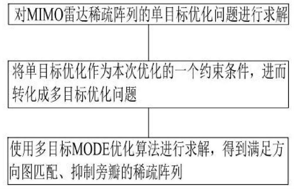
The invention discloses an MIMO radar sparse array optimization method based on an MODE algorithm, and relates to the technical field of radar imaging systems. The method comprises two steps to complete sparse array optimization. On the basis of completing the establishment of a covariance matrix, problem modeling is carried out mainly for sparse array optimization. According to the method, a CA+CA+DE algorithm is used for solving a single-objective optimization problem, then single-objective optimization is used as a constraint condition of the optimization, then the single-objective optimization problem is converted into a multi-objective optimization problem, and finally a multi-objective MODE optimization algorithm is used for solving to obtain a sparse array which meets directional diagram matching and inhibits side lobes. The method can converge to global optimization under the condition that the directional diagram is fixed, and the convergence speed is high.

Description

technical field [0001] The invention relates to the technical field of radar imaging systems, in particular to a method for optimizing a sparse array of MIMO radar based on a MODE algorithm. Background technique [0002] Micro millimeter-wave radar is a low-cost and high-performance sensor with high-precision speed measurement and distance measurement capabilities. Compared with optical sensors such as cameras and lidars, millimeter-wave radar has the advantages of working all day, adapting to various rainy and snowy weather, as well as complex environments such as sand, dust, and smog, with a longer working distance and a wider field of view. And compared to lidar, its cost is also lower. Micro millimeter-wave radar has a wide range of applications, including military and civilian applications. [0003] In order to achieve high-resolution radar imaging, one or more radar chips can generally be used to implement array antennas. In order to reduce costs, the antenna array f...

Claims


Application Information

Patent Timeline
IPC IPC(8): G01S13/89G01S7/02
CPCG01S7/02G01S13/89
Inventor 马月红惠蕙张伟涛朱唐永君王硕
Owner SHIJIAZHUANG TIEDAO UNIV
Learn More