
Automatic focusing device and automatic focusing method for changing image space optical path

A technology of automatic focusing and focusing position, applied in the field of microscope image scanning and processing, can solve problems such as difficult to achieve, and achieve the effect of strong robustness, compact system structure and high focusing accuracy

Inactive Publication Date: 2020-09-15
江苏骠马智能工业设计研究有限公司
View PDF6 Cites 0 Cited by
  • Summary
  • Abstract
  • Description
  • Claims
  • Application Information

AI Technical Summary

Problems solved by technology

[0011] To sum up, when the microscope imaging system scans and acquires images, it is often difficult to take into account factors such as acquisition efficiency, system cost, imaging quality, and compact system structure.

Method used


Image

  • Automatic focusing device and automatic focusing method for changing image space optical path
  • Automatic focusing device and automatic focusing method for changing image space optical path
  • Automatic focusing device and automatic focusing method for changing image space optical path

Examples


Embodiment Construction

[0031] The preferred embodiments of the present invention will be described in detail below in conjunction with the accompanying drawings, so that the advantages and features of the present invention can be more easily understood by those skilled in the art, so as to define the protection scope of the present invention more clearly.

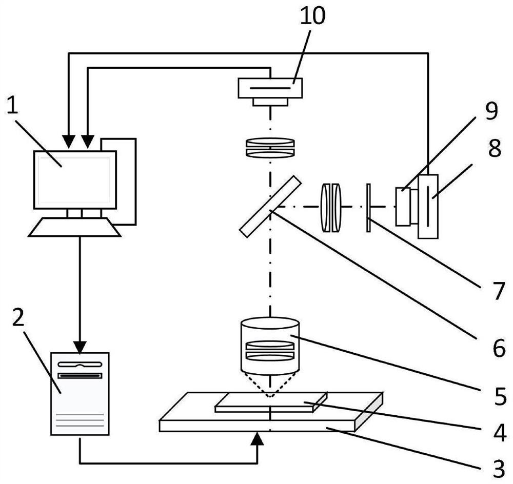
[0032] Such as figure 1The shown automatic focusing device for changing the optical path of the image side includes a computer 1, a motion controller 2, a three-axis motion platform 3, an object to be detected 4, a microscopic objective lens 5, a light splitting element 6, an optical path control element 7, and a focusing camera 8, The camera is equipped with a fine-tuning module 9 and a picture-taking camera 10 . The detected object 4 is placed on the three-axis motion platform 3 and can move along the three directions of X, Y, and Z; the images collected by the focusing camera 8 and the drawing camera 10 are all transmitted to the computer 1 fo...


PUM


Abstract

The invention relates to an automatic focusing device capable of changing an image space optical path, which comprises a computer, a motion controller, a three-axis motion platform, a microscope objective, a light splitting element, an optical path control element, a focusing camera and an image acquisition camera; the optical path control element enables known differences to exist in optical paths of four areas on a focusing camera sensor so as to generate defocusing of different degrees, wherein the out-of-focus degree of the image acquisition camera is different from the out-of-focus degrees of the four regions in the focusing camera; the focusing camera and the image acquisition camera communicate with the computer through signal lines; the computer communicates with the motion controller; and the motion controller communicates with the three-axis motion platform. The invention further discloses an implementation scheme of the automatic focusing method of the device, the current out-of-focus degree can be monitored in real time, real-time tracking focusing can be carried out during flying (motion acquisition), the acquisition efficiency, the system cost and the imaging qualityare considered to the maximum extent, and the system structure is compact.

Description

Technical field: [0001] The invention belongs to the technical field of microscope image scanning and processing, and relates to digital image processing technology and microscope optical path design technology. More specifically, the invention relates to an automatic focusing device for changing the optical path of the image side and an automatic focusing method for the device. Background technique: [0002] In the microscopic imaging system, the higher the resolution of the objective lens, the smaller the depth of field, especially the 20-100 times high-power microscope objective lens, the depth of field is about 1.5-0.5 microns. After the detected object is placed on the motion platform, the height difference of its surface often exceeds the depth of field of the imaging system. Therefore, when the imaging system scans and captures images of the entire surface of the detected object, it is necessary to adjust the focusing height of the imaging system in the Z direction to...

Claims


Application Information

Patent Timeline
Patent Type & Authority Applications(China)
IPC IPC(8): H04N5/232G02B21/36G02B21/24
CPCG02B21/241G02B21/361H04N23/67
Inventor 曹文罗华东周永吴昊季松林
Owner 江苏骠马智能工业设计研究有限公司
Learn More