Grinding device for machining car brake disc

A technology for brake discs and automobiles, applied in the field of auto parts processing, can solve the problems of unsatisfactory grinding effect, poor processing environment, affecting the use of brake discs, etc., to avoid damage to the outer surface, good grinding effect and high practicability. Effect

Active Publication Date: 2020-09-18
XIJING UNIV
View PDF7 Cites 2 Cited by
  • Summary
  • Abstract
  • Description
  • Claims
  • Application Information

AI Technical Summary

Problems solved by technology

During the production process of the brake disc, it is usually formed by stamping. After the stamping is completed, burrs will appear on the surface, so the brake disc needs to be polished, and the burrs on the surface of the brake disc are located on the annular side surface, top surface and top of the brake disc. The edge position, the grinding equipment in the prior art, in order to polish the extra positions on the surface of the brake disc at the same time, generally has a plurality of motors, a plurality of transmission mechanisms, and each motor is equipped with a sand disc to prevent the burrs on the surface of the brake disc. Simultaneous grinding, the grinding method of the existing grinding equipment is not only complex in structure and high in cost, but also due to the gaps between the positions of multiple sand discs, some positions of the brake discs cannot be ground, resulting in The sanding effect is not ideal
[0003] In order to ensure the quality of the grinding, it is necessary to use a fixing fixture to fix the brake disc when grinding the brake disc, and the fixing fixtures in the prior art mostly use screw clamps and other rigid fixtures to clamp from the outside of the brake disc Fixed, because the fixing fixture directly contacts the surface of the brake disc, in the process of fixing the brake disc, it is easy to cause the surface of the brake disc to be damaged, which will affect the use of the subsequent brake disc
[0004] Existing grinding equipment is generally all open when grinding, and there is no cover. During grinding, due to the abrasive material (corundum) on the sand disc and the brake disc rubbing each other violently, a large amount of heat will be generated in the process, thereby Splashes of high-temperature metal debris, namely "Mars", may be generated during grinding, which may splash on the skin of the staff and cause injury to the staff. At the same time, since there is no shelter, the splashed metal debris will fall everywhere Yes, leading to poor processing environment

Method used


Image

  • Grinding device for machining car brake disc
  • Grinding device for machining car brake disc
  • Grinding device for machining car brake disc

Examples


Embodiment Construction

[0033] The following will clearly and completely describe the technical solutions in the embodiments of the present invention with reference to the accompanying drawings in the embodiments of the present invention. Obviously, the described embodiments are only some, not all, embodiments of the present invention. Based on the embodiments of the present invention, all other embodiments obtained by persons of ordinary skill in the art without making creative efforts belong to the protection scope of the present invention.

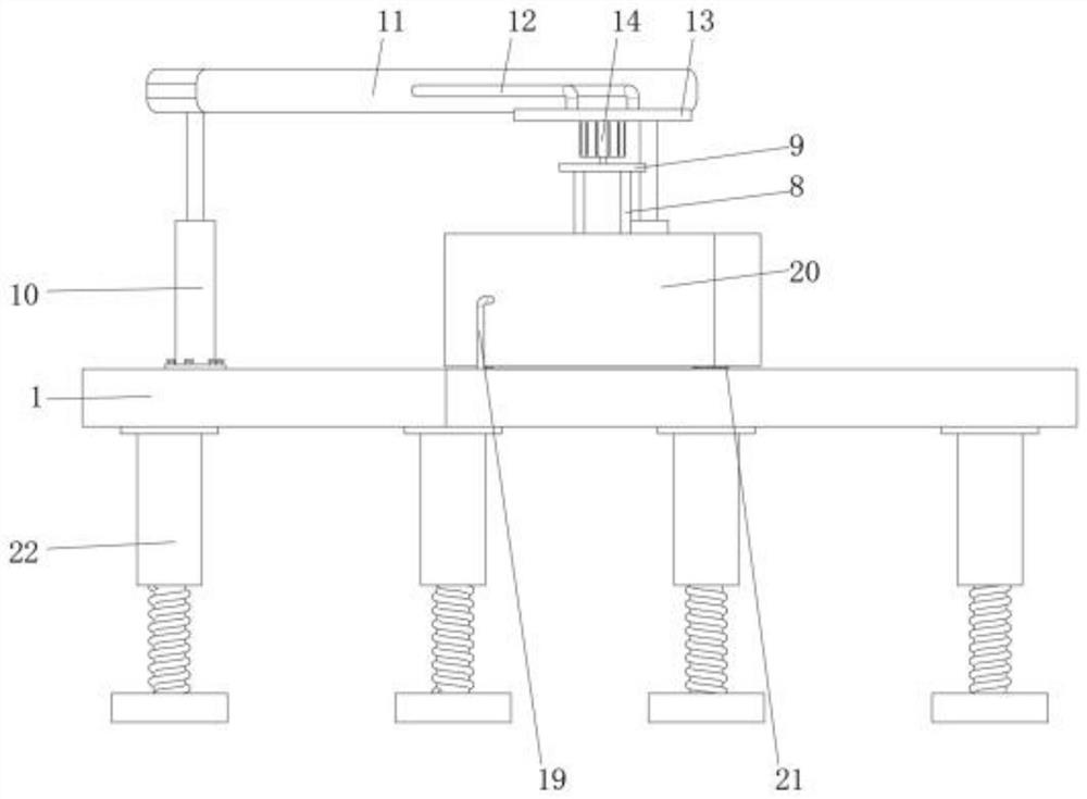
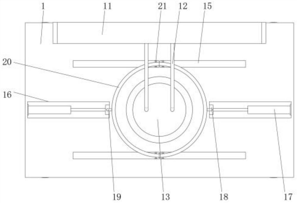
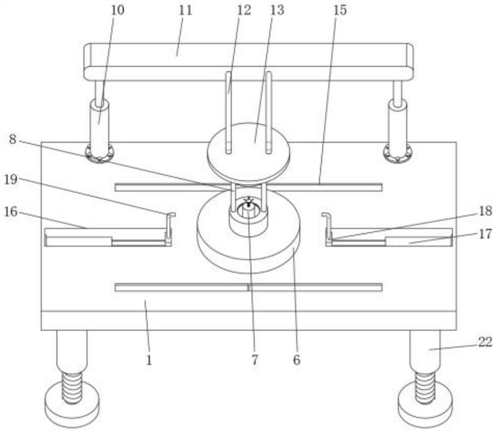
[0034] refer to Figure 1-Figure 12 , a kind of grinding equipment for the production of automobile brake discs, comprising a workbench 1, a placement groove 2 is opened in the middle of the top surface of the workbench 1, a backing disc 3 is placed inside the placement slot 2, and a workpiece 4 to be processed is placed on the top of the backing disc 3 , the outer surface of the workpiece 4 to be processed is provided with a casing 6, the inner wall of the ca...


PUM


Abstract

A grinding device for machining car brake disc includes a workbench. A placement groove is formed in the middle of the workbench. A pad is placed in the placement groove. A workpiece is placed on thetop of the pad. The outer surface of the workpiece is sleeved with a shell. The inner wall of the shell is provided with a sandpan, the sandpan is in connection with the outer surface of a part to beprocessed. A fixing mechanism is installed in the middle of the placing groove, the top of the fixing mechanism sequentially penetrates the part to be processed, the sandpan and the shell and extendsto the outside of the shell, and the fixing mechanism is movably connected with the inner wall of the part to be processed. Two hydraulic rods are fixed on the back side of the workbench. A back plateis fixedly installed between the two hydraulic rods. The front side of the back plate is connected to a passive plate through a connecting rod. The bottom of the passive plate is installed with a drive motor. The output shaft of the drive motor is connected to the connecting plate. The bottom end of a ejector rod is connected with the top of the shell. The grinding device uses the rotation of thehousing and the sandpan to polish the workpiece to be processed, and has the advantages of good polishing effect, non-damaging fixation of the brake disc, and can avoid injury to workers.

Description

technical field [0001] The invention relates to the technical field of automobile parts processing, in particular to a polishing device for automobile brake disc production. Background technique [0002] The car brake disc is in the shape of a convex disc, and it also rotates when the car is moving; the brake caliper clamps the brake disc to generate braking force, which plays the role of deceleration or parking. During the production process of the brake disc, it is usually formed by stamping. After the stamping is completed, burrs will appear on the surface, so the brake disc needs to be polished, and the burrs on the surface of the brake disc are located on the annular side surface, top surface and top of the brake disc. The edge position, the grinding equipment in the prior art, in order to polish the extra positions on the surface of the brake disc at the same time, generally has a plurality of motors, a plurality of transmission mechanisms, and each motor is equipped w...

Claims


Application Information

Patent Timeline
Patent Type & Authority Applications(China)
IPC IPC(8): B24B9/00B24B41/04B24B47/12B24B41/06B24B55/00B24B41/02
CPCB24B9/00B24B41/02B24B41/04B24B41/06B24B47/12B24B55/00
Inventor 叶青张倩寇晨
Owner XIJING UNIV
Why Eureka
Try Eureka