Human-computer interactive humanoid robotic arm
An interactive, robotic arm technology, applied in the field of robotic arms, to achieve fast and convenient connection and prolong service life
- Summary
- Abstract
- Description
- Claims
- Application Information
AI Technical Summary
Problems solved by technology
Method used
Image
Examples
Embodiment 1
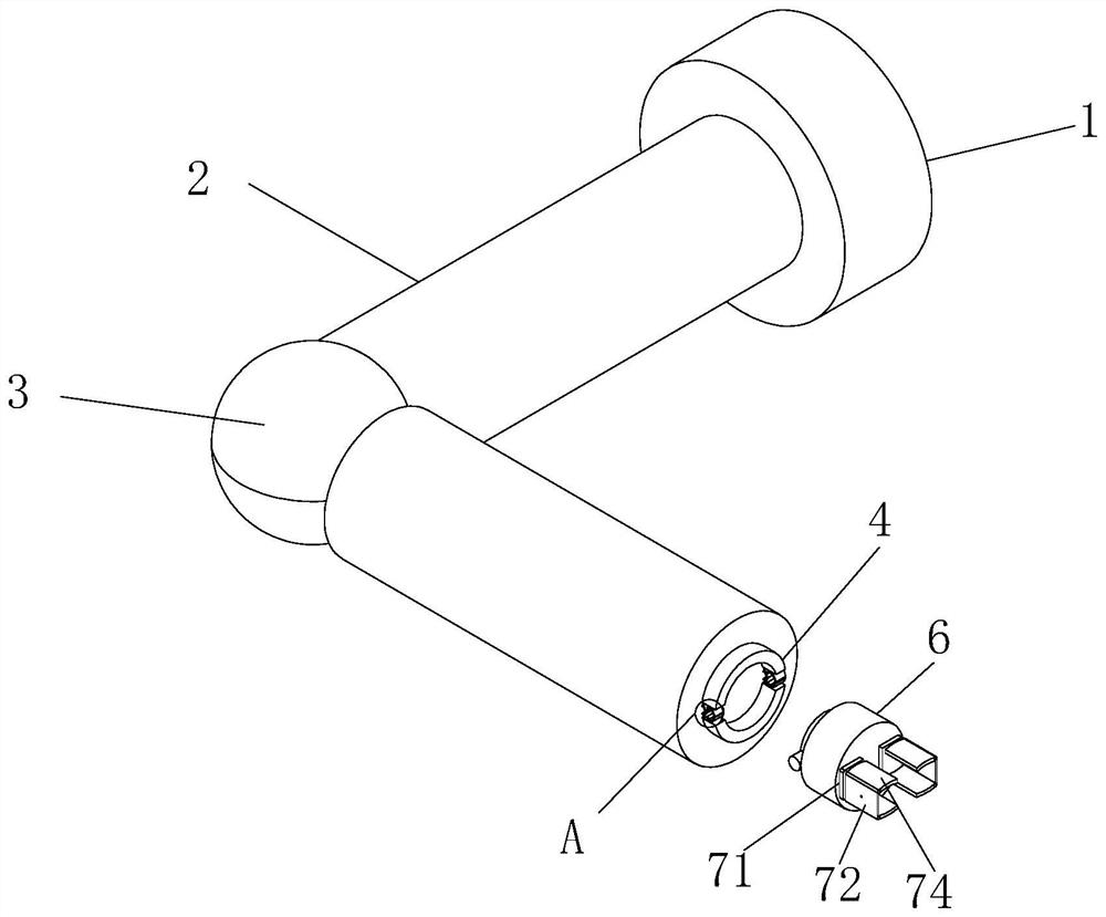
[0031] Example 1: Please refer to Figure 1-2 , human-computer interactive humanoid manipulator, including installation main shaft 1, movable joint 3 and two installation shafts 2, the two installation shafts 2 are fixedly connected with the movable joint 3, the installation main shaft 1 and one installation shaft 2 One end away from the movable joint 3 is fixedly connected, and the other end of the installation shaft 2 that is not connected to the installation main shaft 1 is provided with a mounting ring 4, and the installation ring 4 is fixedly connected with the installation shaft 2, and the mounting ring 4 is cut into two upper and lower parts. There is a circular ring of section, a locking mechanism 5 is arranged between the upper and lower sections of the installation ring 4, and the locking mechanism 5 is fixedly connected with the installation ring 4, and the front side of the installation ring 4 is provided with a connecting seat 6, and the connecting seat 6 is close ...
Embodiment 2
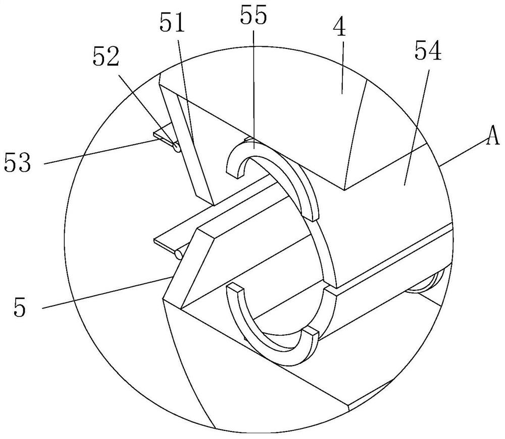
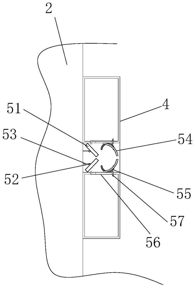
[0032] Embodiment 2: On the basis of Embodiment 1, please refer to Figure 2-3 , the locking mechanism 5 includes a movable plate 51, the movable plate 51 is a slanted plate, the side of the movable plate 51 close to the installation shaft 2 is provided with a fixed shaft 52, the fixed shaft 52 is movably connected with the movable plate 51, and the fixed shaft 52 is installed close to the One side of the shaft 2 is provided with an installation connecting plate 53, which is fixedly connected with the front side wall of the installation shaft 2, and the front side of the movable plate 51 is provided with a clamping plate 54, which is a quarter shape The ring column, the left and right sides of the clamping plate 54 are provided with sliding grooves 55, the sliding grooves 55 are half circular, and the midpoint of the sides of the sliding grooves 55 is fixedly connected with the upper installation ring 4, and the clamping plate 54 The left and right ends are clamped in the slid...
Embodiment 3
[0033] Embodiment three: on the basis of embodiment two, please refer to Figure 2-3 , the inside of the mounting ring 4 is hollow, and the position of the front side of the movable plate 51 in the mounting ring 4 is provided with a push block 56, the push block 56 is an L-shaped rod, and the short side part of the push block 56 extends through the mounting ring 4, pushing A clamping block is arranged between the short side of the block 56 and the wall through which the mounting ring 4 is penetrated. At the same time, the position of the pushing block 56 on the wall of the mounting ring 4 is flexibly connected between the clamping block and the mounting ring 4. The mounting ring 4 is located on the pushing block 56 The position of the front end of the short side is provided with a movable groove whose length matches half of the movable plate 51, and the position of the long side of the push block 56 is adapted to the position when the clamping plate 54 is located at the front s...
PUM
 Abstract
Description
Claims
Application Information
 - R&D
- Intellectual Property
- Life Sciences
- Materials
- Tech Scout
- Unparalleled Data Quality
- Higher Quality Content
- 60% Fewer Hallucinations
Browse by: Latest US Patents, China's latest patents, Technical Efficacy Thesaurus, Application Domain, Technology Topic, Popular Technical Reports.
© 2025 PatSnap. All rights reserved.Legal|Privacy policy|Modern Slavery Act Transparency Statement|Sitemap|About US| Contact US: help@patsnap.com


