Shield receiving end reinforcing structure, reinforcing method and shield receiving method

A technology for strengthening structures and receiving methods, which is applied in the direction of earth cube drilling, mining equipment, tunnels, etc., can solve the problems of consuming large consumables, increasing the workload of construction workers, and increasing construction costs, so as to save consumables and avoid abnormal wear and tear , the effect of reducing workload

Active Publication Date: 2020-09-18
BCEG CIVIL ENG
View PDF15 Cites 0 Cited by
  • Summary
  • Abstract
  • Description
  • Claims
  • Application Information

AI Technical Summary

Problems solved by technology

[0003] The purpose of the present invention is to provide a shield receiving end reinforcement structure, reinforcement method and shield receiving method, so as to solve the problem that the existing end soil reinforcement method is applied to soft soil with good stratum conditions and strong soil self-stability There are technical problems such as large waste, large consumption of consumables, increased workload of construction workers, and increased construction costs during formation

Method used


Image

  • Shield receiving end reinforcing structure, reinforcing method and shield receiving method
  • Shield receiving end reinforcing structure, reinforcing method and shield receiving method
  • Shield receiving end reinforcing structure, reinforcing method and shield receiving method

Examples


Embodiment 1

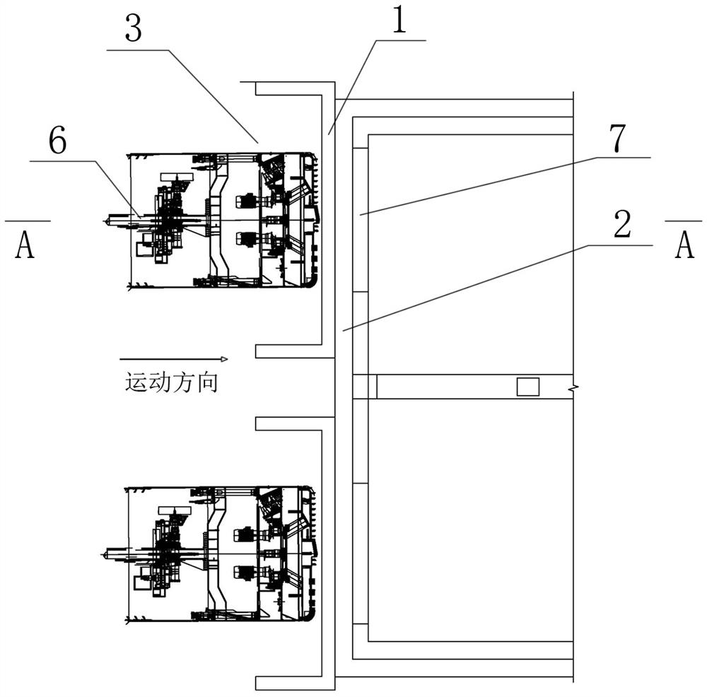
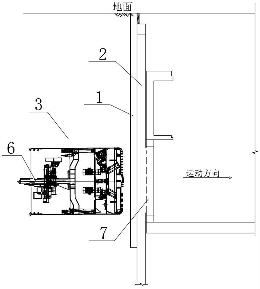
[0054] Such as figure 1 and figure 2 Shown is a shield receiving end, the reinforcement structure 1 of the shield receiving end is arranged in the soil body behind the enclosure structure 2 and one side of the reinforcement structure 1 is in contact with the enclosure structure 2 . The reinforcement structure 1 is a steel member driven vertically into the soil body. It should be noted that in the present invention, "front" refers to the same direction as the direction of movement of the shield machine, and "rear" refers to the direction opposite to the direction of movement of the shield machine.

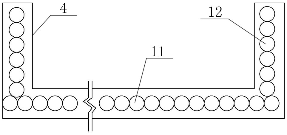
[0055] In this embodiment, the reinforcing structure is cup-shaped, including a cup bottom 11 and two cup walls 12 arranged at the ends of the cup bottom 11 . The thickness of the cup bottom 11 and the cup wall 12 is 40-60cm. The opening of the reinforcement structure 1 of the receiving end of the shield faces the rear of the enclosure structure 2 , and the cup bottom 11 of the ...

Embodiment 2

[0062] Such as Figure 9 and 10 What is shown is the receiving end of the shield machine. The difference from the first embodiment is that the reinforcement structure 1 in this embodiment is in the shape of a straight line, and one side of the reinforcement structure 1 is in contact with the enclosure structure 2 . The reinforcement structure 1 has a width of 40-60 cm. The rest are all the same as in Example 1.

[0063] Such as Figure 11 As shown, the reinforcement structure 1 is a pipe curtain structure formed by closely arranged steel pipe piles.

[0064] Such as Figure 12 As shown, the reinforcement structure 1 is a Larsen steel sheet pile cofferdam structure.

[0065] Such as Figure 13 and 14 As shown, the reinforced structure 1 is an H-shaped steel curtain structure. in Figure 13 The medium H-beams are rotated 90° at intervals. Figure 14 The medium H-beams are arranged in parallel.

[0066] Such as Figure 15 and 16 , the reinforcement structure 1 is an ...


PUM


Abstract

The invention discloses a shield receiving end reinforcing structure, a reinforcing method and a shield receiving method, and belongs to the technical field of shield construction. The shield receiving end reinforcing structure is arranged in a soil body behind an enclosure structure, one surface of the reinforcing structure is connected with the enclosure structure, and the reinforcing structureis a steel component which is vertically driven into the soil body. The reinforcing structure plays a role in reinforcing the soil body, large-volume soil body reinforcement is avoided, consumables and manpower are saved, the workload of construction workers is reduced, and energy consumption and construction cost are reduced. The pull-out component can be repeatedly used, so that the constructioncost is further reduced. According to the shield receiving end reinforcing structure, the reinforcing method and the shield receiving method, the end soil body has no need being integrally reinforced, so that the construction energy consumption is reduced, and the construction cost is saved; and during shield receiving, a shield tunneling machine penetrates through a cavity formed after the component is pulled out, and the low-strength soil body which is not grouted and reinforced is directly cut, so that abnormal abrasion of the shield tunneling machine is avoided, and shied body twisting isprevented.

Description

technical field [0001] The invention relates to the technical field of shield tunnel construction, in particular to a shield tunnel receiving end reinforcement structure, a reinforcement method and a shield tunnel reception method suitable for soft soil formations with good ground conditions at the shield tunnel end and strong soil self-stability. Background technique [0002] Shield reception is one of the key processes in shield tunneling construction, and whether it can be successfully completed is related to the success of shield tunneling. During the excavation process of the shield tunnel, the soil at the end of the shield tunnel must be reinforced, and the reinforcement form must be reasonably selected according to the stratum conditions and construction conditions of different points. Stirring piles or jet grouting piles are often used in soft soil strata. If the stratum is rich in water and the environment is complex, freezing method, grouting + precipitation, box w...

Claims


Application Information

Patent Timeline
Patent Type & Authority Applications(China)
IPC IPC(8): E21D9/00E21D9/06
CPCE21D9/001E21D9/0642E21D9/0671
Inventor 马云新赵洪岩梁宇李生光李森阚宝存
Owner BCEG CIVIL ENG
Why Eureka
Try Eureka