Remote control tower outdoor panoramic camera device and protection structure

A technology of panoramic camera and protective structure, applied in the field of panoramic camera, can solve the problems of long maintenance time, low production efficiency, large windward area of ​​the shield, etc., and achieve the effects of small construction workload, safe and reliable use, and low debugging difficulty.

Pending Publication Date: 2020-09-18
THE SECOND RES INST OF CIVIL AVIATION ADMINISTRATION OF CHINA
View PDF0 Cites 2 Cited by
  • Summary
  • Abstract
  • Description
  • Claims
  • Application Information

AI Technical Summary

Problems solved by technology

[0004] 1. When the panoramic video screen encounters strong winds, especially in coastal areas, the screen of conventional camera monitoring devices shakes a lot, which affects the remote observation of aircraft by control personnel;
[0005] 2. In extreme weather and other conditions, the camera image will be obscured by fog, dust, insects, birds and other factors, which seriously affects the remote command;
[0006] 3. It is difficult to install and debug conventional equipment, and the maintenance time is long
This installation method requires each camera to be wired, outdoor pipes, and then installed and adjusted angles one by one, manually splicing into a panoramic picture, at least two debugging personnel are required to cooperate with the debugging, the workload is heavy, and the production efficiency is low.
In addition, the common camera gimbal structure on the market has less contact surface for camera installation, large windward area of ​​the shield, poor wind resistance performance, and large camera shake in windy weather, which seriously affects the panoramic splicing screen.

Method used


Image

  • Remote control tower outdoor panoramic camera device and protection structure
  • Remote control tower outdoor panoramic camera device and protection structure
  • Remote control tower outdoor panoramic camera device and protection structure

Examples


Embodiment Construction

[0081] Embodiments of the present invention will be described in detail below in conjunction with the accompanying drawings.

[0082] It should be noted that, in the case of no conflict, the following embodiments and the features in the embodiments can be combined with each other; and, based on the embodiments in the present disclosure, those of ordinary skill in the art obtained without creative work All other embodiments belong to the protection scope of the present disclosure.

[0083] It is noted that the following describes various aspects of the embodiments that are within the scope of the appended claims. It should be apparent that the aspects described herein may be embodied in a wide variety of forms and that any specific structure and / or function described herein is illustrative only. Based on the present disclosure one skilled in the art should appreciate that an aspect described herein may be implemented independently of any other aspects and that two or more of t...


PUM


Abstract

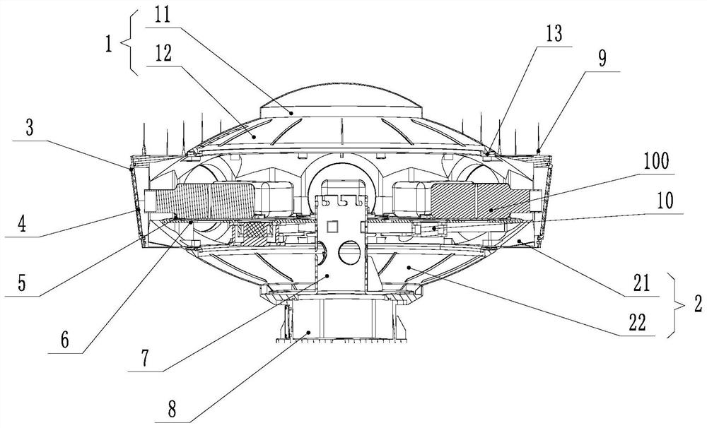
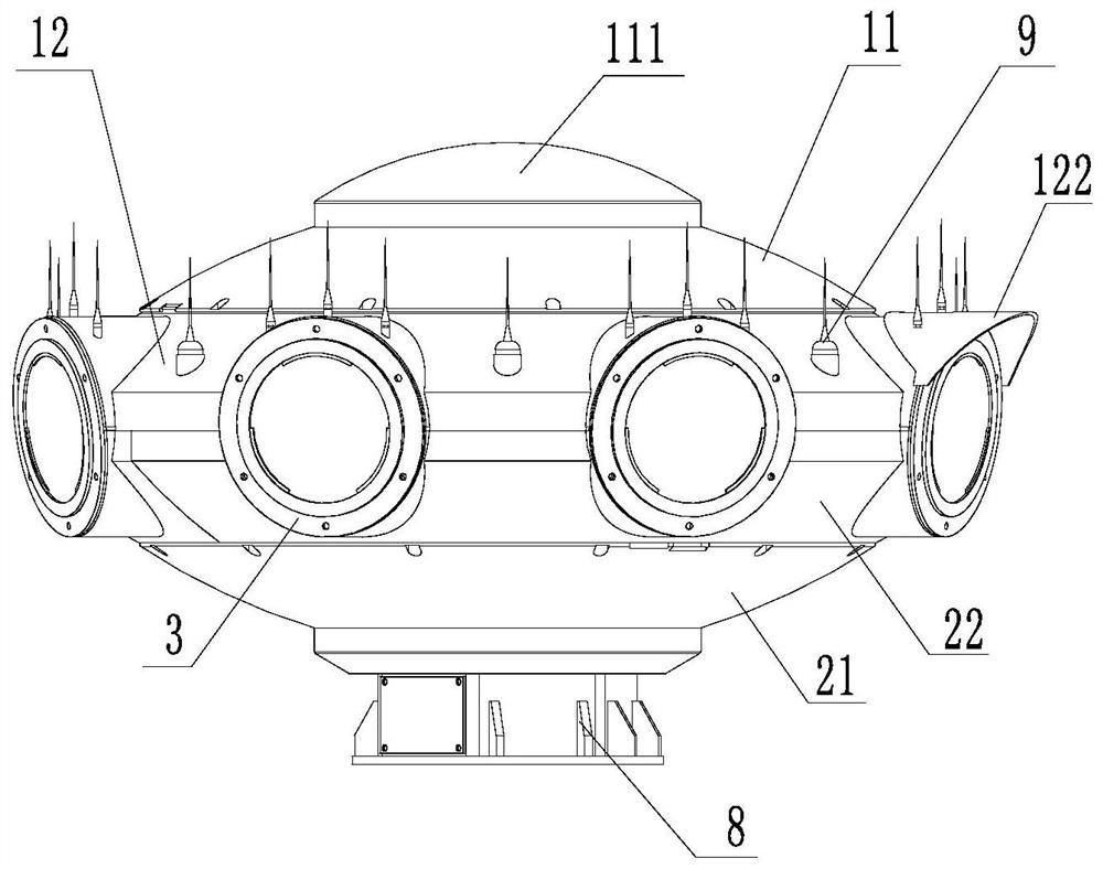
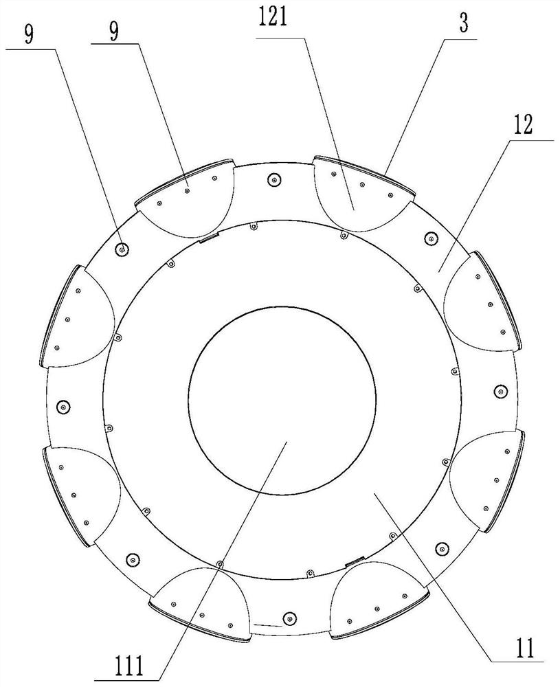
The invention relates to the field of panoramic cameras, in particular to a remote control tower outdoor panoramic camera device and a protection structure. The protection structure comprises an uppershell, a lower shell, fixing plates, a supporting rod, a base, a plurality of fixing supports and lens covers, wherein the upper shell is installed at the top of the lower shell, the base is arrangedat the bottom of the lower shell, an arc top surface is arranged on the upper shell, a plurality of first lens installing parts are uniformly arranged at the bottom of the upper shell along the circumferential direction, an arc bottom surface is arranged at the lower shell, a plurality of second lens installing parts are uniformly arranged at the top of the lower shell along the circumferential direction, the lens covers are installed on the end surfaces of the lens installing parts, the supporting rod is installed in the lower shell, the fixing plates are installed at extending and fixing arms, the fixing supports are installed on the fixing plates, a plurality of cameras are correspondingly installed on the fixing supports, and the radial positions of the fixing supports are adjustablealong the fixing plate. The protection structure has the advantages of being waterproof, dustproof, small in wind resistance and shake, low in debugging difficulty, easy and convenient to maintain andthe like.

Description

technical field [0001] The invention relates to the field of panoramic cameras, in particular to an outdoor panoramic camera device and a protective structure of a remote tower. Background technique [0002] In the command of the airport tower, the panoramic system is a must-have equipment, especially the waterproof, temperature, dustproof, insect-proof, bird-proof, anti-shake, lens self-cleaning and other functions of the panoramic front-end device, which directly affect the stability of the real-time picture of the remote tower system , and ability to operate in severe weather. Therefore, in order for the remote tower system to be practically used, the stable protection function of the front-end equipment must also be realized. [0003] In the actual use of remote towers, the following three problems are often encountered: [0004] 1. When the panoramic video screen encounters strong winds, especially in coastal areas, the screen of conventional camera monitoring devices...

Claims


Application Information

Patent Timeline
Patent Type & Authority Applications(China)
IPC IPC(8): F16M1/00F16M11/04A01M29/32H04N5/225
CPCF16M1/00F16M11/04A01M29/32H04N23/50
Inventor 高勇吴敏王凯姚辉唐墨臻何玄杨樊董子琪
Owner THE SECOND RES INST OF CIVIL AVIATION ADMINISTRATION OF CHINA
Why Eureka
Try Eureka