
Stirrer and smelting furnace with stirrer

A technology of stirrer and stirring paddle, which is applied in the direction of stirring devices, furnaces, furnace materials, etc., can solve the problems of high labor intensity, limited stirring effect, and harsh working environment for workers, achieve uniform and thorough stirring, and avoid space occupation and waste , Improve the effect of mixing uniformity

Active Publication Date: 2020-09-18
湖南森科有色金属有限公司
View PDF5 Cites 3 Cited by
  • Summary
  • Abstract
  • Description
  • Claims
  • Application Information

AI Technical Summary

Problems solved by technology

[0004] In the prior art, when recycling aluminum scrap, the impurities and moisture in the aluminum scrap must be removed first, and then the aluminum scrap that has been preliminarily screened is put into a furnace for melting and stirring to remove slag and other materials mixed with aluminum. and then further purify the molten aluminum, but the process of melting the existing scrap aluminum is mainly to pour a part of the scrap aluminum into the furnace, and then wait for the scrap aluminum to melt, then manually stir it with a steel stirring spoon for more than ten minutes , and then add a part of waste aluminum to melt, and then stir, because the temperature in the furnace is very high (usually around 750-800 degrees Celsius), this makes the working environment of the workers harsh and labor-intensive. Although there are some furnaces in the prior art A stirring paddle is installed for stirring, but the paddle is driven by a motor to rotate, which can only be used for some drum-shaped furnaces, and for some cuboidal furnaces, especially those with a rectangular cross-section, the stirring effect is limited. Therefore, now Some cuboid furnaces still have room for improvement

Method used


Image

  • Stirrer and smelting furnace with stirrer
  • Stirrer and smelting furnace with stirrer
  • Stirrer and smelting furnace with stirrer

Examples


Embodiment Construction

[0028] The present invention will be further described in detail below in conjunction with the accompanying drawings and embodiments.

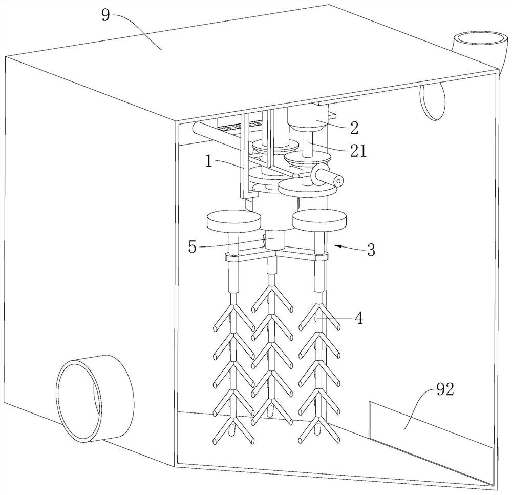
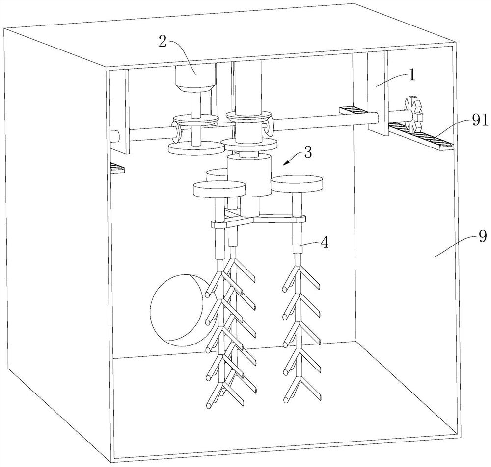
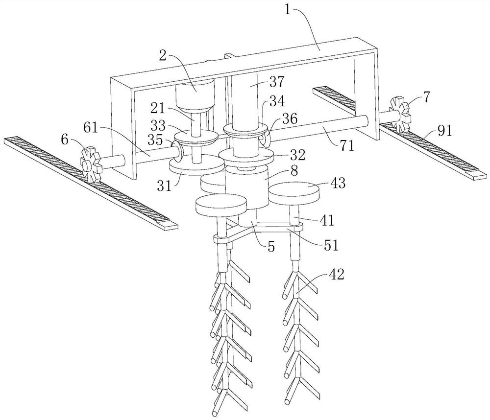
[0029] A furnace with a stirrer, incorporating Figure 1-5 As shown, it includes a housing 9 and an agitator arranged in the housing 9. The cross section of the housing 9 is rectangular, and guide rails 91 are arranged on the opposite inner walls of the housing 9, and the guide rails 91 are along the length direction of the housing 9. extend. The housing 9 is provided with a material inlet, a material outlet and a liquid outlet, and the bottom of the housing 9 is inclined. The feed inlet is set above the shell 9 for putting scrap aluminum into the furnace, and the liquid outlet is located on the higher side of the bottom of the shell 9, and the molten aluminum liquid is guided to the next process through the guide pipe In the refining furnace, the discharge port of the shell 9 is located at the lower side of the bottom of the shell 9, and is...


PUM


Abstract

The invention discloses a stirrer and a smelting furnace with the stirrer. The stirrer comprises a traveling support, a driving motor, a transmission structure and stirring paddles, wherein the driving motor is arranged on the traveling support, an output shaft of the driving motor is connected with the stirring paddles through the transmission structure and drives the stirring paddles to rotate,and a first traveling wheel and a second traveling wheel are respectively arranged on two sides of the traveling support; and the output shaft of the driving motor is respectively connected with the first traveling wheel and the second traveling wheel through the transmission structure, drives the first traveling wheel and the second traveling wheel to synchronously rotate, and drives the traveling support and the stirring paddles arranged on the traveling support to horizontally move. The driving motor is arranged to control the two traveling wheels to rotate on guide rails, so that the traveling support is driven to travel in the smelting furnace, the smelting furnace can be stirred, and the stirring is more uniform and thorough.

Description

technical field [0001] The invention relates to the technical field of nonferrous metal smelting, in particular to a stirrer and a melting furnace with the stirrer. Background technique [0002] High-purity aluminum has good ductility and can usually be rolled into extremely thin aluminum foil or extremely fine aluminum wire. At present, mechanical rolling can be used to produce independent aluminum foil with a thickness of 0.4 microns, while electrodeposition can produce thicknesses up to 7.5 microns. Nano-scale aluminum film, the aluminum film must be attached to the plastic base film, high-purity aluminum has low deformation resistance, high electrical conductivity and good plasticity, and is mainly used in scientific research, electronics industry, chemical industry and manufacturing High-purity alloys, laser materials and some other special purposes. [0003] my country is a big producer and consumer of aluminum products. However, my country's bauxite resources are ver...

Claims


Application Information

Patent Timeline
Patent Type & Authority Applications(China)
IPC IPC(8): F27D27/00
CPCF27D27/00F27M2003/13
Inventor 陈晓龙
Owner 湖南森科有色金属有限公司
Learn More