Patch double pin header and double female header for metal substrate

A metal substrate, double-row needle technology, applied in the direction of fixed connection, contact parts, electrical components, etc., can solve the problems of labor-hours, low work efficiency, joint damage to the thermal insulation layer, etc., to improve work efficiency and reliable circuit connection. , to avoid the effect of short circuit

Pending Publication Date: 2020-09-18
桂林海威科技股份有限公司
View PDF0 Cites 0 Cited by
  • Summary
  • Abstract
  • Description
  • Claims
  • Application Information

AI Technical Summary

Problems solved by technology

LED light boards usually use metal substrates to achieve a good heat dissipation effect. When the LED light board needs to be connected to other circuit boards, since the A side (front) of the LED light board is equipped with lamp beads, the line connected to the LED light board The board can only be installed on the B side (back side) of the LED light board. In order to avoid open circuit, the existing technology is to open a through hole on the surface of the metal substrate, and manually weld multiple mutually insulated wires on the A side of the LED light board as required. The wire passes through the through hole, and the other end of the wire is welded to the circuit board set on the B side (back) of the LED light board. This method consumes man-hours and has low work efficiency. The uncertainty of manual welding leads to poor welding quality. Guaranteed, the connection between the metal substrate and the circuit board circuit on the back is not reliable, which reduces the stability of the circuit
[0003] B

Method used


Image

  • Patch double pin header and double female header for metal substrate
  • Patch double pin header and double female header for metal substrate
  • Patch double pin header and double female header for metal substrate

Examples


Embodiment 1

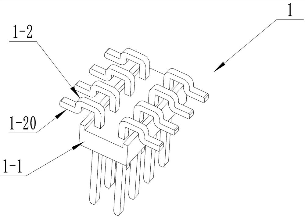
[0027] The first embodiment is further optimized. The front, rear, left and right side walls of the insulating body are flat and have no grooves. The side wall surfaces of the prior art pin header insulating body have grooves that are easy to divide. In this embodiment, the grooves are removed. After the groove, it is convenient to process and manufacture the insulating body and the hole of the metal substrate, and prevent the adverse consequences of liquid leakage when the front of the metal substrate needs to be filled with glue.

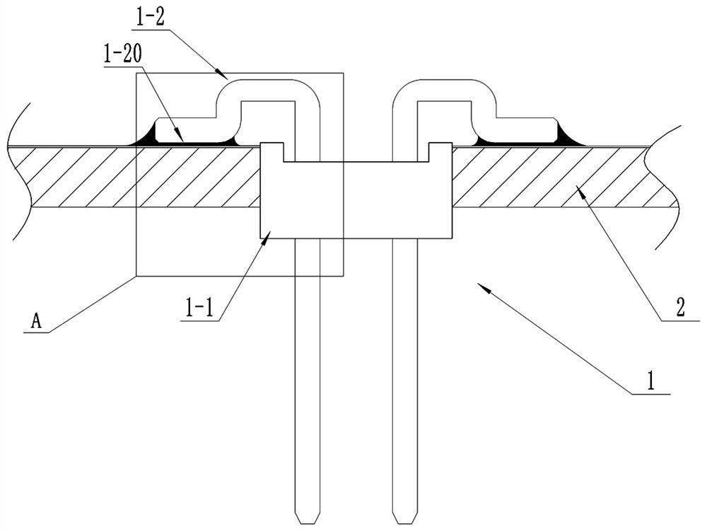
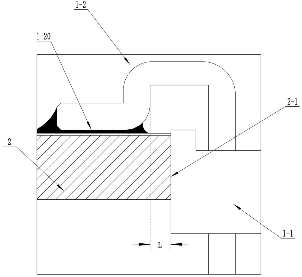
[0028] see Figure 4 , Figure 4 Shown is the front view of the patch double pin header for the metal substrate according to the second embodiment of the present invention. The difference between the second embodiment and the first embodiment is the elbow, and other structures are the same. The elbow part of the second embodiment is bent twice, the first bend is folded outward and downward, and the second bend is folded horizontally outward, so t...


PUM


Abstract

The invention relates to a pin header and a female header structure, particularly to a patch double pin header and a double female header for a metal substrate. The patch pin header is characterized in that a left elbow pin header and a right elbow pin header penetrate through the upper top surface and the lower top surface of an insulating body and are distributed in a bilateral symmetry mode; the elbow portion of the elbow pin header is provided with a patch surface; the patch surface is parallel to the upper top surface or the lower top surface; the patch surface of the left elbow pin header is arranged on the left side of the insulating body; the patch surface of the right elbow pin header is arranged on the right side of the insulating body; and the elbow portion of the elbow pin header is provided with at least two elbows, so that the distance between the patch surface of the elbow portion and the side wall of the insulating body on the corresponding side is greater than a safe distance. The double female header structure can refer to the double pin header. According to the invention, the patch double pin header or double female header is installed in the through holes of themetal substrate, so that automatic welding can be achieved, the working efficiency is improved, the metal substrate and the circuit board are connected in a sleeved mode through the pin header and the female header so as to achieve reliable circuit connection and convenient disassembly and assembly.

Description

technical field [0001] The invention relates to a pin and mother structure, in particular to a patch double pin and double mother used for a metal substrate. Background technique [0002] The metal substrate is a metal circuit board material, which belongs to the general electronic components. It is composed of a thermally conductive insulating layer, a metal plate and a metal foil. It has the characteristics of special magnetic conductivity, excellent heat dissipation, high mechanical strength, and good processing performance. The LED light board usually uses a metal substrate to achieve a good heat dissipation effect. When the LED light board needs to be connected to other circuit boards, since the A side (front) of the LED light board is provided with lamp beads, the circuit connected to the LED light board The board can only be set on the B side (back side) of the LED light board. In order to avoid open circuit, the existing technology is to open through holes on the sur...

Claims


Application Information

Patent Timeline
IPC IPC(8): H01R12/57H01R12/70H01R12/71H01R13/02H01R13/46
CPCH01R12/57H01R12/7082H01R12/718H01R13/02H01R13/46
Inventor 覃沿日雷红梅杨尚李雪祥汤谷心
Owner 桂林海威科技股份有限公司
Why Eureka
Try Eureka