Method for optimizing configuration place and optimal compensation capacity of reactive equipment of electric power system

A power system and compensation capacity technology, applied in reactive power compensation, reactive power adjustment/elimination/compensation, circuit devices, etc., can solve problems such as easy occurrence of local optimum, lack of randomness in particle position update, etc., and achieve global search Improve ability and convergence speed, avoid the effect of premature convergence

Active Publication Date: 2020-09-18
SICHUAN UNIV
View PDF3 Cites 1 Cited by
  • Summary
  • Abstract
  • Description
  • Claims
  • Application Information

AI Technical Summary

Problems solved by technology

At the same time, the capacity allocation of reactive power compensation devices is also a problem to be discussed in nonlinear programming
[0003] When calculating the optimal compensation capacity based on the traditional standard particle swarm algorithm, it is necessary to set parameters such as local learning factor and global learning factor, which has a certain adverse effect on finding the best parameters of the optimization model. At the same time, the particle position update lacks randomness, and local optimal problem

Method used


Image

  • Method for optimizing configuration place and optimal compensation capacity of reactive equipment of electric power system
  • Method for optimizing configuration place and optimal compensation capacity of reactive equipment of electric power system
  • Method for optimizing configuration place and optimal compensation capacity of reactive equipment of electric power system

Examples


Embodiment Construction

[0039] In order to make the purpose, technical solution and advantages of the present invention clearer, the present invention will be further elaborated below in conjunction with the accompanying drawings.

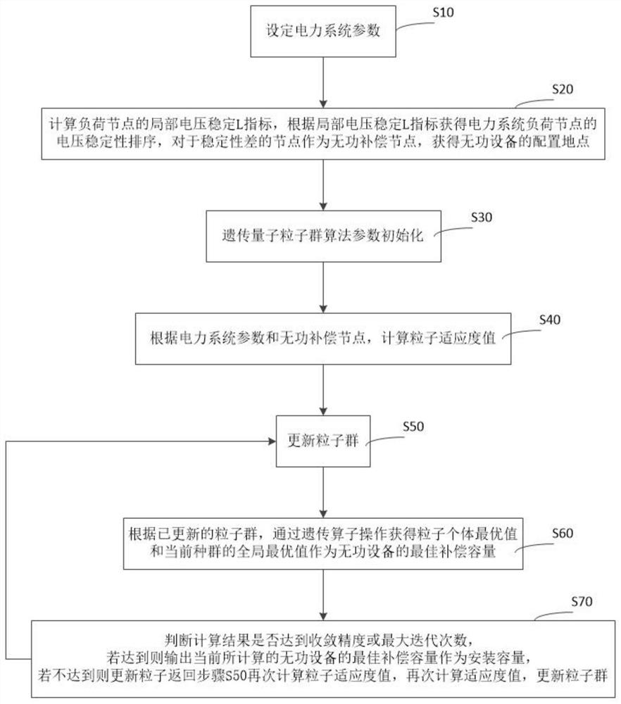
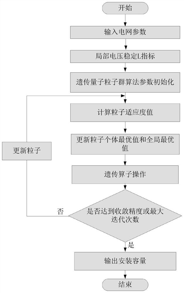
[0040] In this example, see figure 1 and figure 2 As shown, the present invention proposes a power system reactive equipment configuration site and an optimal compensation capacity optimization method, including steps:

[0041] S10, setting power system parameters;

[0042] S20, calculate the local voltage stability L index of the load node, obtain the voltage stability ranking of the power system load node according to the local voltage stability L index, and use the node with poor stability as a reactive power compensation node to obtain the configuration location of the reactive power equipment;

[0043] S30, parameter initialization of the genetic quantum particle swarm optimization algorithm;

[0044] S40, calculating the particle fitness value according to the p...


PUM


Abstract

The invention discloses a method for optimizing a configuration place and optimal compensation capacity of reactive equipment of a power system. The method comprises the following steps: setting powersystem parameters; obtaining a voltage stability sequence of load nodes of the power system according to the local voltage stability L index, and taking the nodes with low stability as reactive compensation nodes; initializing parameters; calculating a particle fitness value; updating the particle swarm; according to the updated particle swarm, obtaining a particle individual optimal value and aglobal optimal value of the current swarm through genetic operator operation to serve as the optimal compensation capacity of the reactive power equipment; and judging whether a calculation result reaches convergence precision or the maximum iteration frequency, if YES, outputting the currently calculated optimal compensation capacity of the reactive power equipment as the installation capacity, and if NO, updating the particles, returning to calculate the particle fitness value again, calculating the fitness value again, and updating the particle swarm. According to the invention, the configuration place and the optimal compensation capacity of the reactive power equipment of the power system can be quickly and effectively obtained.

Description

technical field [0001] The invention belongs to the technical field of electric power systems, and in particular relates to an optimization method for disposing locations of reactive power equipment and optimal compensation capacity in electric power systems. Background technique [0002] As the scale of the power system continues to increase, it is not possible to configure reactive power compensation devices for each load node in a certain area of ​​the system due to insufficient reactive power in the system. Although this ensures the stability of the system voltage to a large extent, the cost is too high. , the control method is redundant and complicated, and has no practical engineering application value. Determining the optimal compensation point of reactive power compensation equipment is a key issue in the research of reactive power planning in power systems. At the same time, the capacity allocation of reactive power compensation devices is also a problem to be disc...

Claims


Application Information

Patent Timeline
IPC IPC(8): H02J3/18G06Q10/04G06Q50/06G06N3/00G06N3/12G06N10/00
CPCH02J3/18H02J3/1871G06Q10/04G06Q50/06G06N3/006G06N3/126G06N10/00H02J2203/10H02J2203/20Y02E40/30Y02E40/70Y04S10/50
Inventor 钟俊焦兴伟
Owner SICHUAN UNIV
Why Eureka
Try Eureka