
Power supply device, and electric vehicle and power storage device provided with said power supply device

A power supply device and motor technology, applied in battery/battery traction, battery, circuit, etc., can solve the problems of increased expansion and increased strength, and achieve the effect of improving thermal insulation properties and preventing thermal runaway.

Inactive Publication Date: 2020-09-18
SANYO ELECTRIC CO LTD
View PDF8 Cites 2 Cited by
  • Summary
  • Abstract
  • Description
  • Claims
  • Application Information

AI Technical Summary

Problems solved by technology

[0003] In addition, it is generally known that the packaging can of the battery cell expands during charging and discharging, or when there is an abnormality such as deterioration or short circuit, and the amount of expansion tends to increase when the energy density per unit volume is high.
Therefore, when configuring a battery pack composed of a plurality of battery cells, there is a problem that the strength required for the restraint structure for preventing the battery cells from swelling increases.

Method used


Image

  • Power supply device, and electric vehicle and power storage device provided with said power supply device
  • Power supply device, and electric vehicle and power storage device provided with said power supply device
  • Power supply device, and electric vehicle and power storage device provided with said power supply device

Examples


Embodiment Construction

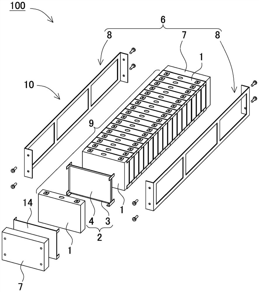
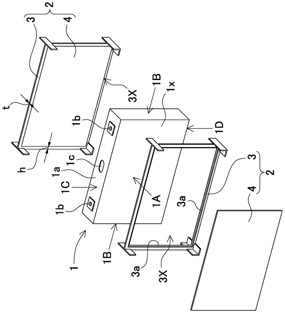
[0026] First, one focus of the present invention will be described. According to the power supply device disclosed in Patent Document 1, since a hole is provided in the center of the separator stacked between adjacent battery cells, expansion of the battery cells can be absorbed through the hole. However, in this separator, since a relatively large space is formed in the center, air convection cannot be suppressed, and there is a problem that it is difficult to suppress heat transfer between adjacent battery cells. Therefore, it is important to study a structure that can absorb the expansion of the battery cells without providing a gap between the adjacent battery cells, and that can cut off the heat conduction between the battery cells to prevent the induction of thermal runaway.

[0027] A power supply device according to a certain aspect of the present invention can be defined as follows. The power supply device includes: a battery stack 9 formed by stacking a plurality of...


PUM

PropertyMeasurementUnit
thermal conductivityaaaaaaaaaa
melting pointaaaaaaaaaa
thicknessaaaaaaaaaa

Abstract

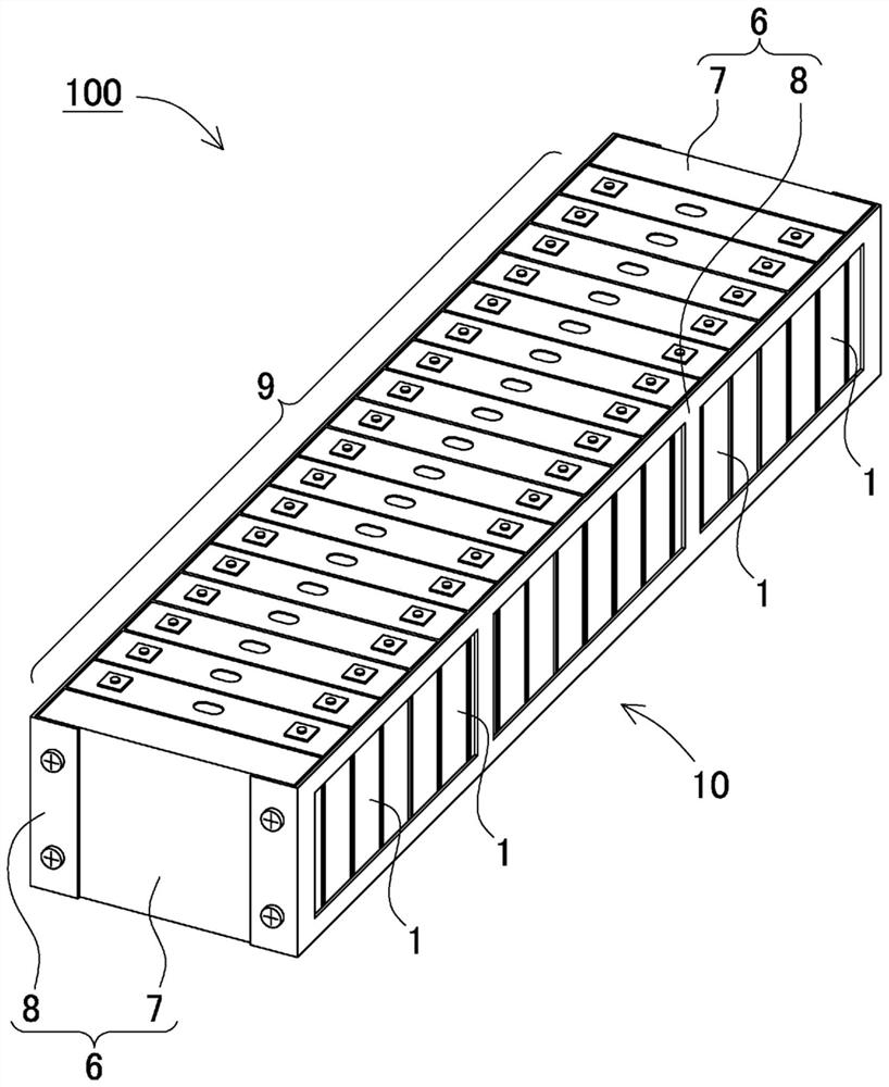
A power storage device, while absorbing expansion of the battery cells, prevents inducing thermal runaway by blocking heat conduction between battery cells, and is provided with: a battery stack formed by stacking multiple battery cells (1); separators (2) arranged between the battery cells (1); and a fixing member for fastening the battery stack in the stacking direction. The separator (2) is formed from a perimeter frame (3) and a thermal insulation base material (4) provided in the opening (3X) of the perimeter frame (3). The perimeter frame (3) is arranged on the outer periphery of the stacking surface (1A) of the battery cell (1) and has an opening (3X) on the inside, and the thermal insulation base material (4) has flexibility that allows deformation when pressed by the expanding stacking surface (1A) of the battery cell (1). The perimeter frame (3) is more rigid than the thermal insulation base material (4), the perimeter frame (3) specifies the interval between adjacently stacked battery cells (1), and the flexible thermal insulation base material (4) has a structure that absorbs expansion of the stacking surface (1A) of the battery cell (1).

Description

technical field [0001] The present invention relates to a power supply device in which a plurality of battery cells are laminated, and more particularly to a power supply device for a motor that is mounted on an electric vehicle such as a hybrid vehicle, a fuel cell vehicle, an electric vehicle, or an electric motorcycle to drive the vehicle Or a power supply device for a large current used in household use, power storage applications in factories, etc., and an electric vehicle and a power storage device equipped with the power supply device. Background technique [0002] A power supply device in which a plurality of battery cells are stacked is used in various applications. Such a power supply device preferably has a high capacity, and in recent years studies have been conducted to increase the capacity of battery cells. In particular, the purpose is to increase the energy density per unit volume. As the capacity of the battery cells increases, the energy possessed by one...

Claims


Application Information

Patent Timeline
Patent Type & Authority Applications(China)
IPC IPC(8): H01M2/10H01M10/613H01M10/625H01M10/647H01M10/6555H01M10/658B60L50/64
CPCH01M10/625H01M10/658Y02E60/10H01M2220/20H01M50/24H01M50/249B60L50/64H01M50/209H01M50/264H01M50/222H01M50/289
Inventor 桥本裕之高品智一小平绘里
Owner SANYO ELECTRIC CO LTD
Learn More