
A flexible direct-lit backlight source and display device thereof

A direct type, backlight technology, applied in the direction of nonlinear optics, optics, instruments, etc., can solve the problem that the backlight cannot meet the large curvature and free bending

Active Publication Date: 2020-10-27
SHENZHEN CHINA STAR OPTOELECTRONICS SEMICON DISPLAY TECH CO LTD
View PDF6 Cites 0 Cited by
  • Summary
  • Abstract
  • Description
  • Claims
  • Application Information

AI Technical Summary

Problems solved by technology

[0005] An object of the present invention is to provide a flexible direct-type backlight and its display device, which can solve the problem that the current direct-type backlight cannot meet the free bending of large curvature

Method used


Image

  • A flexible direct-lit backlight source and display device thereof
  • A flexible direct-lit backlight source and display device thereof
  • A flexible direct-lit backlight source and display device thereof

Examples


Embodiment 1

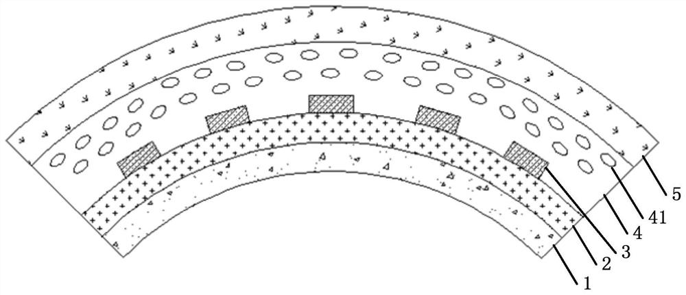
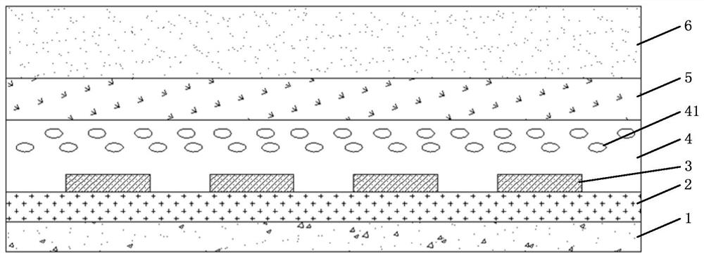
[0028] Such as figure 1 As shown, the present invention provides a flexible direct backlight, which includes a graphene heat dissipation coating 1, a flexible circuit board 2, a mini LED 3, an air bubble glue layer 4 and an optical film layer 5 arranged in sequence.

[0029] Wherein the composition material Graphene (Graphene) of described graphene heat dissipation coating 1 is a kind of by carbon atom with sp 2 The hybrid orbitals form a hexagonal two-dimensional carbon nanomaterial with a honeycomb lattice. Since graphene has very good thermal conductivity, it can well transmit the heat generated by the backlight to the outside.

[0030] Wherein the flexible printed circuit board 2 (English full name: Flexible Printed Circuit, FPC for short) is disposed on the graphene heat dissipation coating 1 . The flexible circuit board 2 is made of polyimide or polyester film as the base material. Therefore, the flexible circuit board 2 has the characteristics of high wiring density,...

Embodiment 2

[0037] In the following, only the differences between the present embodiment and the first embodiment will be described, and the similarities will not be repeated here.

[0038] Such as image 3 As shown, the present invention also provides a display device, including the above-mentioned flexible direct backlight and a flexible liquid crystal screen 6 . The flexible liquid crystal screen 6 is pasted on the flexible direct-type backlight through an adhesive.

[0039] The constituent materials of the adhesive include at least one of silica gel, epoxy glue and acrylic, and at least one of UV light curing agent, inorganic particles and inert gas.


PUM

PropertyMeasurementUnit
diameteraaaaaaaaaa

Abstract

A flexible direct-LED backlight device and a display apparatus comprising the same. The backlight device comprises a graphene heat dissipation coating (1), a flexible circuit board (2), a mini light-emitting diode (3), a bubble adhesive layer (4), an optical film layer (5), and a flexible liquid crystal display screen (6) which are sequentially disposed. At least two bubbles (41) are provided in the bubble adhesive layer (4). The bubble adhesive layer (4) having the tiny bubbles (41) is disposed between the optical film layer (5) and the mini light-emitting diode (3), such that light emitted by the mini light-emitting diode (3) is reflected when passing through the bubble adhesive layer (4), thereby effectively diffusing the light emitted by the mini light-emitting diode (3), and reducing the thickness of the bubble adhesive layer (4). The configuration can improve thermal insulation properties of the bubble adhesive layer (4), increase thermal resistance, reduce heat transferred from the backlight device to the liquid crystal display screen, reduce the temperature of the liquid crystal display screen, increase the viscosity of liquid crystal materials, and reduce light leakage. The configuration can also improve flexibility of the backlight device. When the backlight device is in a bent state, good shrinkage properties of the bubbles can offset the material deformation caused by a portion of the materials being bent, such that the backlight device can meet the demand for improved curvature.

Description

technical field [0001] The invention relates to the field of display technology, in particular to a flexible direct-lit backlight source and a display device thereof. Background technique [0002] At present, backlight sources of light-emitting diodes (English: Light-Emitting Diode, LED for short) are divided into side-light type and direct-light type. Edge-lit backlight is a backlight made by setting linear or point light sources on the side of a specially designed light guide plate. The principle of the light guide plate is to use the dot distribution on the bottom of the light guide acrylic plate to destroy the interference phenomenon of light, and evenly convert the line light source into a surface light source. The shadow to the reflection point is used to improve the brightness of the panel and ensure the uniformity of the brightness of the panel. The quality of the light guide plate has a great influence on the backlight. According to the needs of actual use, the li...

Claims


Application Information

Patent Timeline
Patent Type & Authority Patents(China)
IPC IPC(8): G02F1/13357
CPCG02F1/133603G02F1/133606G02F1/133608G02F1/133628
Inventor 樊勇
Owner SHENZHEN CHINA STAR OPTOELECTRONICS SEMICON DISPLAY TECH CO LTD
Learn More