
Surface microstructure array with water mist collecting function and molding method thereof

A microstructure array and molding method technology, applied in 3D object support structures, manufacturing tools, additive manufacturing, etc., can solve the problems of low water mist collection efficiency, low molding efficiency, and difficulty in forming functional surface microstructures, and achieve improved The effect of water mist recycling efficiency, reducing molding time, improving molding accuracy and molding quality

Inactive Publication Date: 2020-09-22
CHANGSHA UNIVERSITY OF SCIENCE AND TECHNOLOGY
View PDF0 Cites 1 Cited by
  • Summary
  • Abstract
  • Description
  • Claims
  • Application Information

AI Technical Summary

Problems solved by technology

[0003] In view of the above-mentioned technical problems such as the low water mist collection efficiency of the existing super-hydrophobic functional surface, the difficulty in forming the microstructure of the functional surface, and the low molding efficiency, the present invention aims to provide a water mist collection device for a resin-based water mist collector. The surface microstructure array and its forming method

Method used


Image

  • Surface microstructure array with water mist collecting function and molding method thereof
  • Surface microstructure array with water mist collecting function and molding method thereof
  • Surface microstructure array with water mist collecting function and molding method thereof

Examples


Embodiment Construction

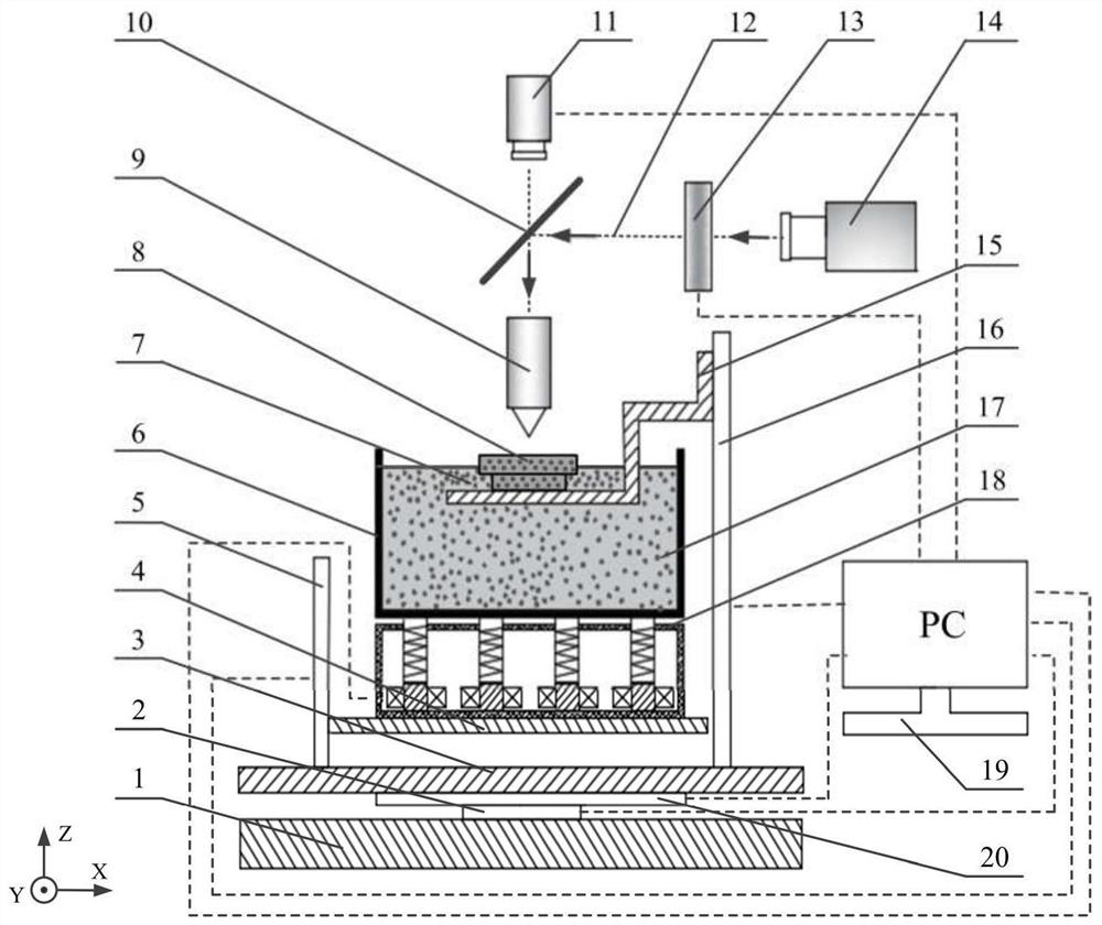
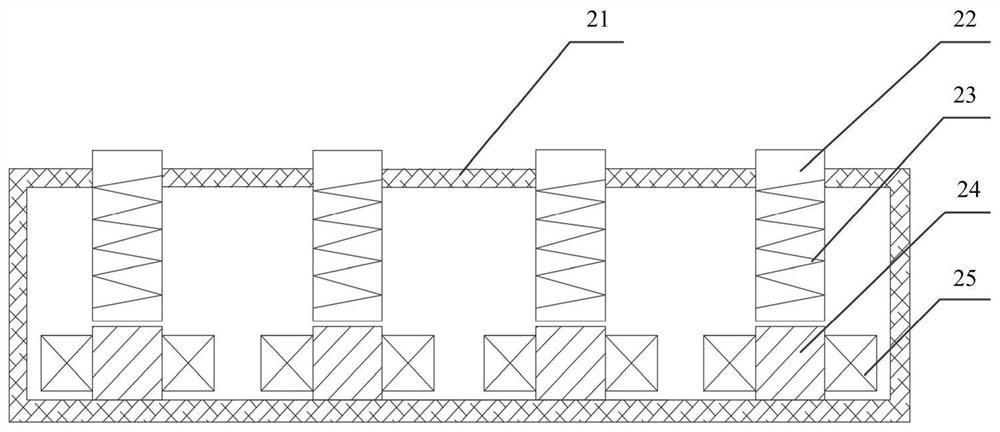
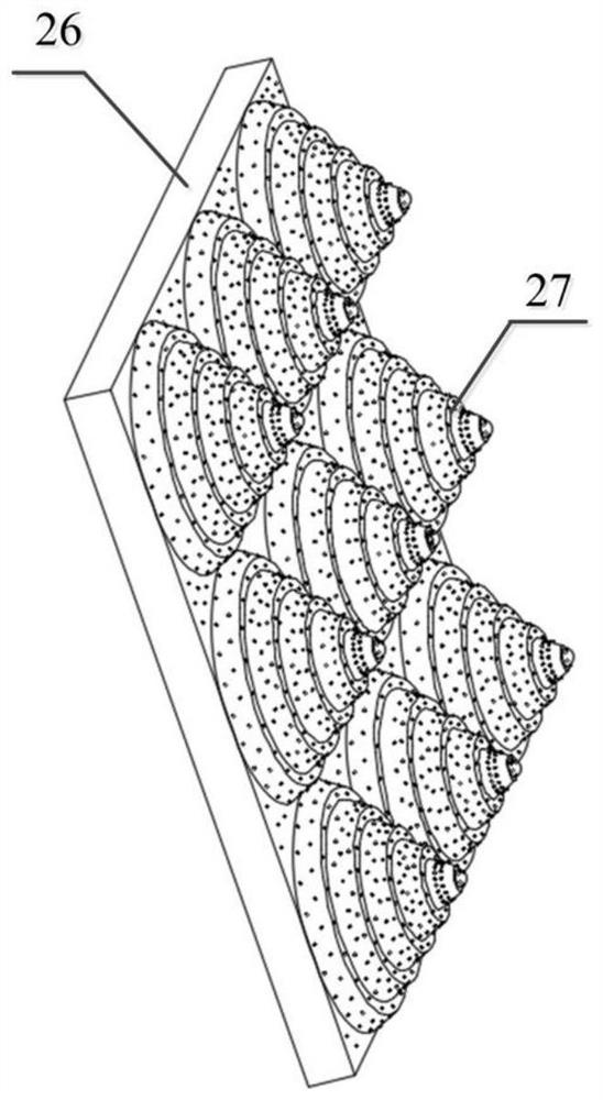
[0021] See attached Figure 1~4 , the single microstructure of the surface microstructure array with water mist collection function is a conical pyramid structure 28, the structure is a multi-layer conical superimposition, the material is photosensitive resin 7, and the radius at the bottom of each layer of conical frusta is decreasing layer by layer, respectively 5µm, 4µm, 3µm, 2µm, 1µm; the inclination angle of the conical bus bar of each layer is constant at 64°, and its height is constant at 1µm; the horizontal and vertical spacing between two adjacent microstructures is 2µm; on the surface of the microstructure, there are Nanoparticles 17 form a micro / nano composite structure with the frusto-pyramidal structure 28; a plurality of the above-mentioned composite structures are evenly distributed on the target surface 27 of the molding to form a surface microstructure array 26.

[0022] The forming method of the surface microstructure array 26 with the function of collecting w...


PUM


Abstract

The invention discloses a surface microstructure array with a water mist collecting function and a molding method thereof. A single microstructure of the surface microstructure array is a circular truncated cone pyramid structure, the structure is formed by overlaying multiple layers of circular truncated cones, the material is photosensitive resin, and the bottom radius of each layer of circulartruncated cone is reduced layer by layer and forms a micron structure; nano particles are distributed on the surface of the microstructure to form a micron / nano composite structure with the circular truncated cone pyramid structure; and a plurality of composite structures are uniformly distributed on the target surface of a molded part, namely, the surface microstructure array is formed. The molding method for the surface microstructure array utilizes a set of electromagnetic assisted vibration surface to project a micro-stereolithography system and follows certain steps to complete the preparation. The surface microstructure array provided by the invention can increase the contact area between the microstructure and the water mist, and improve the recovery efficiency of the water mist; the molding method provided by the invention reduces the agglomeration of nanoparticles, realizes uniform distribution and improves the forming accuracy and quality through the high-frequency vibrationof an electromagnetic auxiliary vibration device; and a mobile platform of a forming system can move horizontally and linearly in the Y-axis and X-axis directions, the area of a molding layer and thesize of the molded part are expanded, the molding time is reduced, and the molding efficiency is improved.

Description

technical field [0001] The invention belongs to the technical field of surface modification and 3D printing and molding, and in particular relates to a surface microstructure array with water mist collecting function and a molding method thereof. Background technique [0002] In recent years, due to climate change and the intensification of human activities, many parts of the world are facing the problem of water shortage. At present, the main means to alleviate the shortage of water resources are seawater desalination and water mist collection; among them, the latter has a wider application area and lower cost than the former. The traditional mesh collector is subject to double constraints when collecting water mist: on the one hand, the coarse mesh water mist collector cannot capture micron-sized droplets, and the recovery efficiency is low; on the other hand, the fine mesh water mist recovery The device is easy to block, which also reduces the recovery efficiency. The l...

Claims


Application Information

Patent Timeline
Patent Type & Authority Applications(China)
IPC IPC(8): B29C64/124B29C64/20B29C64/386B29C64/264B29C64/30B29C64/245B29C64/379B29C64/232B29C64/236B33Y30/00B33Y40/00B33Y40/20B33Y50/00B33Y80/00
CPCB33Y30/00B33Y40/00B33Y50/00B33Y80/00B29C64/124B29C64/20B29C64/232B29C64/236B29C64/245B29C64/264B29C64/30B29C64/379B29C64/386B33Y40/20
Inventor 唐昆李典雨易香怀陈紫琳张明军毛聪吴茵
Owner CHANGSHA UNIVERSITY OF SCIENCE AND TECHNOLOGY
Learn More