Large-range flow meter and large-range flow measuring method

A large-scale, flowmeter technology, applied in volume measurement, liquid/fluid solid measurement, measuring devices, etc., can solve the problems of increasing the liquid flow resistance of the main pipeline, inconvenient maintenance, etc., and achieve simple structure, high sensitivity, and index sensitive effect

Active Publication Date: 2020-09-22
NINGBO HUACHENG VALVE
View PDF5 Cites 2 Cited by
  • Summary
  • Abstract
  • Description
  • Claims
  • Application Information

AI Technical Summary

Problems solved by technology

[0002] Commonly used flowmeters include orifice flowmeters, electromagnetic flowmeters, turbine flowmeters, positive displacement flowmeters, and float flowmeters. Basically, all flowmeters need to be installed in the main channel of the infusion pipeline, which is inconvenient for maintenance and increases Larger main pipe liquid flow resistance

Method used


Image

  • Large-range flow meter and large-range flow measuring method
  • Large-range flow meter and large-range flow measuring method
  • Large-range flow meter and large-range flow measuring method

Examples


Embodiment 1

[0027] Embodiment 1 Manual type large-range flowmeter:

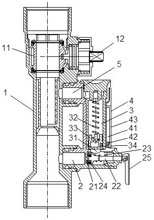
[0028] Such as Figure 1-4 As shown, this embodiment describes in detail the specific structure and usage method of the wide-range flowmeter in the present invention in conjunction with a flowmeter-type balance valve.

[0029] The flow meter type balancing valve includes a valve body 1, and a ball valve 11 and a valve stem 12 are installed in the valve body 1.

[0030] The balancing valve includes a large-range flowmeter, and the large-range flowmeter includes a housing detachably installed on the side of the valve body 1 . Compared with the main passage in the valve body, a bypass passage of the valve body is formed in the casing. The bypass channel includes a liquid inlet channel 2 , a measuring channel 3 and a liquid outlet channel 5 connected in sequence, and both the liquid inlet channel 2 and the liquid outlet channel 5 are connected to the valve body 1 .

[0031] In this structure, the measuring channel 3 inclu...

Embodiment 2

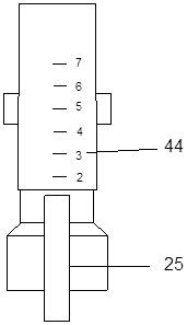
[0054] Embodiment 2 Automatic wide-range flowmeter

[0055] The automatic wide-range flowmeter in this embodiment has the same structure as the manual wide-range flowmeter in terms of liquid inlet channel, measurement channel, and liquid outlet channel.

[0056] The difference lies in the opening control mechanism, which includes:

[0057] Such as Figure 5 As shown, the inner end of the piston is provided with a pressure sensor, the piston rod is connected to the motor, the motor is connected to the controller, and the controller is connected to the switch and the pressure sensor; when the switch is turned on, the controller obtains the water pressure of the pressure sensor Information, when the water pressure information is in the first preset value interval, the motor drives the piston rod to move, so that the piston leaves the piston valve seat to the first stroke, the liquid inlet channel is opened, and maintains a first fixed opening; when the water pressure information...


PUM


Abstract

The invention discloses a large-range flow meter and a flow adjusting method thereof. The large-range flow meter comprises a shell, the shell internally comprises a liquid inlet channel, a measuring channel and a liquid outlet channel which are connected in sequence, and the liquid inlet channel is connected with the measuring channel through a channel inlet; a spring and a floater are arranged inthe measuring channel; a piston valve seat and a piston rod are arranged in the liquid inlet channel, the piston rod is sleeved with a reset spring, and a piston is arranged on the piston rod; and the flow meter further comprises an opening degree control mechanism which drives the piston rod to move and drives the piston rod to generate at least two stroke changes from an initial state. The large-range flow meter can provide a large-range flow measurement function, and theoretically, the flow range measured by the flow meter can be infinitely large due to the fact that the opening degree control mechanism drives the piston rod to generate a plurality of stroke changes from the initial state. The flow meter and flow measuring method have the advantages of simple structure, sensitive index, high sensitivity and large measurement range.

Description

technical field [0001] The invention relates to the technical field of valves, in particular to a large-range flowmeter and a large-range flow measurement method. Background technique [0002] Commonly used flowmeters include orifice flowmeters, electromagnetic flowmeters, turbine flowmeters, positive displacement flowmeters, and float flowmeters. Basically, all flowmeters need to be installed in the main channel of the infusion pipeline, which is inconvenient for maintenance and increases Larger main pipeline liquid flow resistance. Contents of the invention [0003] The present invention provides a large-range flowmeter without the flowmeter installed in the valve body and an accurate flow adjustment method, so as to realize the flow adjustment method that the flowmeter does not affect the liquid flow in the valve body and can accurately adjust the flow rate of the valve body. [0004] To achieve the above object, the present invention adopts the following technical sol...

Claims


Application Information

Patent Timeline
Patent Type & Authority Applications(China)
IPC IPC(8): G01F1/52G01F15/00
CPCG01F1/52G01F15/001
Inventor 王朝阳林方杰连超燕吕强胡朝辉徐东荣
Owner NINGBO HUACHENG VALVE
Why Eureka
Try Eureka