
Robot speed reducer fault detection system based on big data analysis

A technology of fault detection and reducer, which is applied in the field of detection system, can solve the problems of unable to detect the speed of the reducer, unable to shut down the reducer, stop the working system, etc., to achieve easy promotion and use, easy discovery and processing, and reduce work difficulty Effect

Pending Publication Date: 2020-09-22
上海仪电智能科技有限公司
View PDF0 Cites 0 Cited by
  • Summary
  • Abstract
  • Description
  • Claims
  • Application Information

AI Technical Summary

Problems solved by technology

[0004] The purpose of the present invention is to provide a robot reducer fault detection system based on big data analysis, so as to solve the problems in the use of the existing reducer proposed in the above-mentioned background technology, because the reducer needs to decelerate the rotating object , so it is necessary to ensure that the reducer is in normal operation, otherwise it will cause the rotating object to break and collide due to the high speed, resulting in a greater safety hazard, and even stop the entire working system, resulting in greater economic losses. The existing reducer does not have a fault detection system, which cannot detect the speed of the reducer, and cannot close and stop the reducer in time.

Method used


Image

  • Robot speed reducer fault detection system based on big data analysis
  • Robot speed reducer fault detection system based on big data analysis
  • Robot speed reducer fault detection system based on big data analysis

Examples


Embodiment Construction

[0033] The following will clearly and completely describe the technical solutions in the embodiments of the present invention with reference to the accompanying drawings in the embodiments of the present invention. Obviously, the described embodiments are only some, not all, embodiments of the present invention. Based on the embodiments of the present invention, all other embodiments obtained by persons of ordinary skill in the art without making creative efforts belong to the protection scope of the present invention.

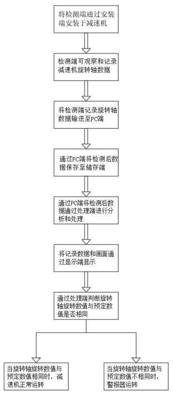
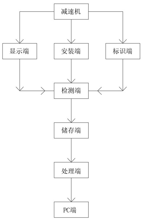
[0034] see Figure 1 to Figure 3 , the present invention provides a technical solution: a robot reducer fault detection system based on big data analysis, including a reducer, a PC terminal, a detection terminal, a display terminal, an installation terminal, an identification terminal, a storage terminal, a processing terminal, a reducer and a PC terminal The reducer is connected to the detection end through the installation end, the reducer is connected to th...


PUM


Abstract

The invention discloses a robot speed reducer fault detection system based on big data analysis. The robot speed reducer fault detection system comprises a speed reducer, a PC terminal, a detection terminal, a display terminal, an installation terminal, an identification terminal, a storage terminal and a processing terminal. The speed reducer is connected with the PC terminal. The speed reducer is connected with the detection terminal through the installation terminal, the speed reducer is linearly connected with the display terminal, a rotating shaft is arranged on one side of the speed reducer, and the identification terminal is arranged on the side wall of the rotating shaft; the PC terminal is linearly connected with the detection terminal, the PC terminal is linearly connected with the display terminal, the PC terminal is linearly connected with the storage terminal, and the PC terminal is connected with the processing terminal; the detection terminal and the display terminal arearranged, the functionality of the speed reducer is improved, the rotating speed of the rotating shaft of the speed reducer is effectively calculated through detection and calculation of the detection terminal on the rotating shaft of the speed reducer, it is ensured that the rotating shaft is in a normal running state, and when the rotating shaft of the speed reducer is in an improper rotating speed state, alarm processing can be conducted through the detection terminal.

Description

technical field [0001] The invention belongs to the technical field of detection systems, and in particular relates to a fault detection system for a robot reducer based on big data analysis. Background technique [0002] Big data refers to a collection of data that cannot be captured, managed, and processed by conventional software tools within a certain period of time. It is a massive, high-growth rate that requires a new processing model to have stronger decision-making power, insight and discovery, and process optimization capabilities. And diversified information assets, with the development of science and technology, the field of big data has also developed rapidly. The existing big data can be analyzed by intelligent robots to make limit value analysis, making big data analysis, screening and observation more convenient , and based on the big data analysis of the reducer, it is not only convenient to use, but also can further reduce potential safety hazards and ensure...

Claims


Application Information

Patent Timeline
IPC IPC(8): G01M99/00H04N5/76H04W4/38G08C17/02
CPCG01M99/008H04N5/76H04W4/38G08C17/02
Inventor 邱婕高鹏周兆滨徐瑜杨之晨
Owner 上海仪电智能科技有限公司
Learn More