Super capacitor cycle life test device and test method

A technology for supercapacitors and testing devices, which can be used in measuring devices, environmental/reliability testing, and electrical measurement. It can solve problems such as large power loss and inconsistent pulse widths of charge and discharge currents, and achieve low energy consumption and avoid uneven temperature rise. The effect of stabilizing and improving test accuracy

Pending Publication Date: 2020-09-22
RENERGY ELECTRIC TIANJIN
View PDF0 Cites 5 Cited by
  • Summary
  • Abstract
  • Description
  • Claims
  • Application Information

AI Technical Summary

Problems solved by technology

[0003] The present invention is proposed in order to overcome the problems of excessive power loss and inconsistency of charge and discharge current pulse width in the cycle life test of supercapacitor in the prior art, and its purpose is to provide a supercapacitor cycle life test device and test methods

Method used


Image

  • Super capacitor cycle life test device and test method
  • Super capacitor cycle life test device and test method

Examples


Embodiment 1

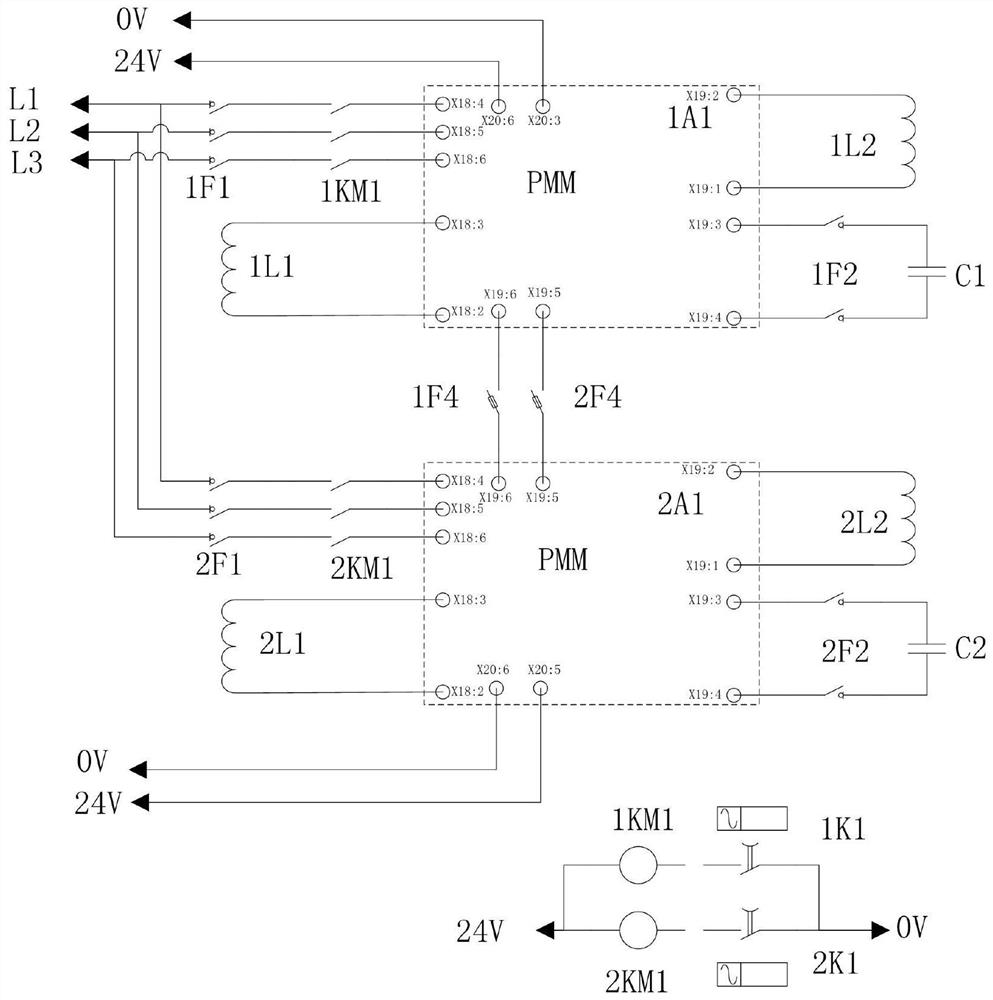
[0034] Such as figure 1 As shown, a supercapacitor cycle life testing device includes No. Ⅰ driver 1A1 and No. Ⅱ driver 2A1 connected by a common bus;

[0035] No. Ⅰ driver 1A1 is connected in series with No. Ⅰ contactor 1KM1 and No. Ⅰ starting circuit breaker 1F1 in sequence, and then connected to the power grid to obtain power, and No. Ⅰ driver 1A1 is respectively connected with No. Ⅰ filter inductor 1L1, No. Ⅰ step-up inductor 1L2 and No. Ⅰ tested Supercapacitor C1;

[0036] No. Ⅱ driver 2A1 is connected in series with No. Ⅱ contactor 2KM1 and No. Ⅱ starting circuit breaker 2F1 in sequence, and then connected to the power grid to obtain power, and No. Ⅱ driver 2A1 is respectively connected to No. Ⅱ filter inductor 2L1, No. Ⅱ step-up inductor 2L2 and No. Ⅱ to be tested Supercapacitor C2;

[0037] No. Ⅰ contactor 1KM1 and No. Ⅱ contactor 2KM1 carry out the on-off control through No. Ⅰ time relay 1K1 and No. Ⅱ time relay 2K1 respectively.

[0038] The control power of the N...

Embodiment 2

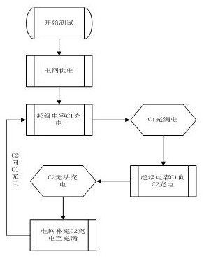
[0045] Such as figure 2 Shown, based on embodiment 1, the supercapacitor cycle life test method of application embodiment 1 device comprises the following steps:

[0046] (ⅰ) Start the test, close No. Ⅰ starting circuit breaker 1F1, No. Ⅱ starting circuit breaker 2F1, No. 1 fuse 1F4 and No. Ⅱ fuse 2 F4, and No. 1 time relay 1K1 controls No. 1 contactor 1KM1 to pull in and connect Grid-powered No. 1 driver 1A1 charges No. 1 supercapacitor C1 under test until it is fully charged;

[0047] (ii) Disconnect No. Ⅰ contactor 1KM1, and No. Ⅰ tested supercapacitor C1 supplies power to No. Ⅱ driver 2A1, and supplies power to No. Ⅱ supercapacitor C2 under test until No. Ⅱ tested supercapacitor C2 cannot continue charging. At this time Close the No. Ⅱ contactor 2KM1, and it will be supplemented by the power grid until it is fully charged;

[0048] (Ⅲ) Disconnect No. Ⅱ contactor 2KM1, and use No. Ⅱ driver 2A1 as No. 1 supercapacitor C1 to be tested, until C1 can no longer be charged, it...


PUM


Abstract

The invention discloses a super capacitor cycle life test device and test method. The device comprises two drivers which are connected through a common bus, wherein the drivers are powered by a powergrid through starting a circuit breaker and a contactor, the tested super capacitor is used as a backup power supply of the drivers and is respectively connected to the two drivers, and a time relay controls the contactor to supplement the super capacitor which is not fully charged. The test method is carried out in a super capacitor mutual charging mode, there is no discharge load, the energy consumption is extremely low in a long-time cycle life test, and the cost is low. In addition, a driver PMM bus is used as transfer in the charging and discharging processes, the current pulse width consistency is good, adverse factors of unstable temperature rise, non-uniform discharge depth and the like in the traditional method and device are well avoided, and the test accuracy is greatly improved.

Description

technical field [0001] The invention belongs to the field of supercapacitor testing for a pitch system of a wind power generating set, and in particular relates to a supercapacitor cycle life testing device and a testing method. Background technique [0002] With the continuous development of the wind power industry and the vigorous progress of offshore wind power, all aspects have been greatly improved compared with the originally developed wind power equipment. The safety and stability of the pitch system has been paid more and more attention. As the backup power supply of the pitch system, super capacitors, Its reliability application has attracted the most attention before entering the market. The research on the health status and failure characteristics of supercapacitors has become a hot topic nowadays, and it is more obvious in life testing. -Constant current consumption load mode, this kind of test process, a great waste of electric energy and the actual current puls...

Claims


Application Information

Patent Timeline
Patent Type & Authority Applications(China)
IPC IPC(8): G01R31/00
CPCG01R31/003
Inventor 李晓峰韩昊王帅武鹏豆建鹏
Owner RENERGY ELECTRIC TIANJIN
Why Eureka
Try Eureka