Switch matrix channel fault diagnosis method and system

A switch matrix and fault diagnosis technology, which is applied in the direction of circuit breaker testing, etc., can solve problems such as low efficiency, complicated commissioning operation process, and lack of effective detection, so as to reduce manual intervention or human factors, and reduce operating costs and complexity , Improve the efficiency of testing and application

Active Publication Date: 2020-09-22
CHINA ELECTRONIS TECH INSTR CO LTD
View PDF25 Cites 0 Cited by
  • Summary
  • Abstract
  • Description
  • Claims
  • Application Information

AI Technical Summary

Problems solved by technology

However, even if the test results show that there is a fault in the channel, it is impossible to accurately diagnose and locate the fault location of the channel, and it is necessary to perform manual judgment and positioning through repeated disassembly, commissioning and testing.
In practical applications, the test scale of microwave semiconductor devices (integrated circuits) is usually large, and the channel scale and complexity of the corresponding switch matrix to meet the requirements are relatively high.
[0007] In summary, the inventor believes that the traditional method not only lacks the technical means to effectively detect the real state, but also the commissioning operation process is complicated and inefficient, and it is difficult to effectively meet the maintenance guarantee of switch matrix (type) products and microwave semiconductor devices ( Integrated circuit) related application requirements and technical requirements for multi-parameter and high-efficiency testing

Method used


Image

  • Switch matrix channel fault diagnosis method and system
  • Switch matrix channel fault diagnosis method and system
  • Switch matrix channel fault diagnosis method and system

Examples


Embodiment 1

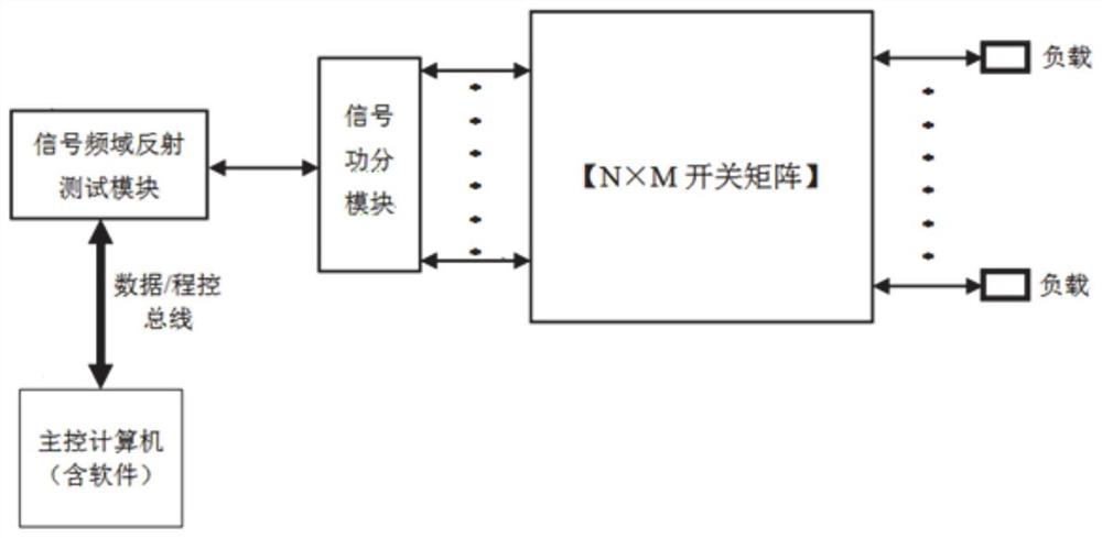
[0032] Such as figure 1 As shown, this embodiment provides a switch matrix channel fault diagnosis method, through which the rapid detection of switch matrix (type) product channel fault diagnosis can be realized, and multi-channel rapid detection and fault diagnosis positioning can be completed at one time. include:

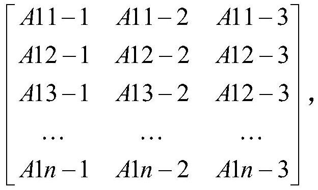
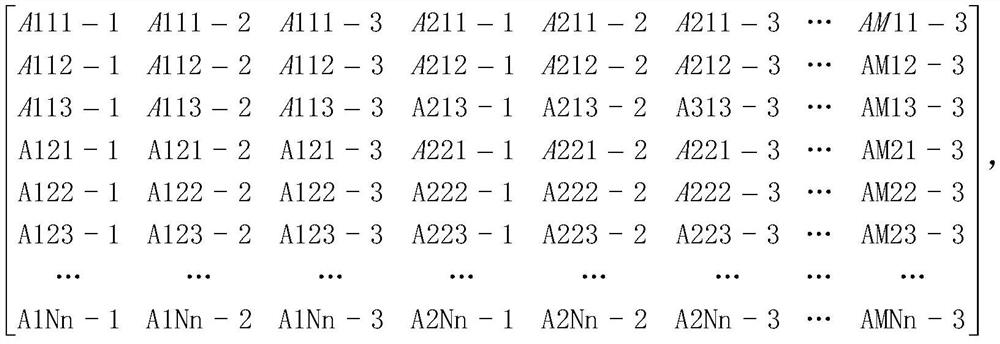
[0033] S1: Build a test channel matrix for the channel where the switch to be tested is located in the switch matrix;

[0034] S2: Perform a reflection signal test on the detection node in the test channel matrix, judge whether the detection node is in a reflection state by preset reflection signal threshold, and construct a test channel detection node matrix;

[0035] S3: Compare the test channel detection node matrix with the normal channel detection node matrix to obtain the fault point channel;

[0036] S4: The detection node of the fault point channel locates the location where the reflected signal occurs based on the frequency domain reflection, that is, the loca...

Embodiment 2

[0054] This embodiment provides a switch matrix channel fault diagnosis system, including:

[0055] The test channel building module is used to build a test channel matrix for the channel of the switch to be tested in the switch matrix;

[0056] The reflection signal test module is used to test the reflection signal of the detection node in the test channel matrix, judge whether the detection node is in the reflection state by preset reflection signal threshold, and construct the test channel detection node matrix;

[0057] The comparison module is used to compare the test channel detection node matrix with the normal channel detection node matrix to obtain the fault point channel;

[0058] The positioning module is used to locate the location where the reflected signal occurs on the detection node of the fault point channel based on the frequency domain reflection, that is, the location of the fault point.


PUM


Abstract

The invention discloses a switch matrix channel fault diagnosis method and system. The method comprises the steps: constructing a test channel matrix for a channel where a switch to be tested is located in a switch matrix; performing reflection signal test on the detection nodes in the test channel matrix, judging whether the detection nodes are in a reflection state or not through a preset reflection signal threshold, and constructing a test channel detection node matrix; comparing the test channel detection node matrix with a normal channel detection node matrix to obtain a fault point channel; and based on frequency domain reflection, positioning the position of a reflected signal, namely the position of the fault point, for the detection node of the fault point channel. Rapid detectionand fault diagnosis positioning of multiple channels are realized, and the uncertainty problem of false alarm generated by an indirect equivalent method is solved according to effective detection ofthe real physical connection state of the channels constructed by the switch matrix.

Description

Technical field [0001] The invention relates to the technical field of microwave testing, in particular to a switch matrix channel fault diagnosis method and system. Background technique [0002] The statements in this section merely provide background information related to the present invention, and do not necessarily constitute prior art. [0003] With the rapid development of microwave semiconductor devices (integrated circuits) and their technologies, the integrated functions and technical characteristics of microwave semiconductor devices (integrated circuits) have been continuously improved. There are more and more test parameters that characterize their corresponding functions and technical characteristics. It is also getting bigger and bigger. Correspondingly, the application of switch matrix products to meet this demand in microwave semiconductor device testing has become more and more extensive. [0004] Using traditional methods, the internal switch status detection and ...

Claims


Application Information

Patent Timeline
Patent Type & Authority Applications(China)
IPC IPC(8): G01R31/327
CPCG01R31/327
Inventor 郭敏王亚海朱学波丁志钊周辉王尊峰
Owner CHINA ELECTRONIS TECH INSTR CO LTD
Why Eureka
Try Eureka