Feeding tank for animal husbandry, having washing function
A technology of feeding troughs and functions, applied in the field of feeding troughs for livestock, to achieve the effect of not easily catching cold and improving cleaning efficiency
- Summary
- Abstract
- Description
- Claims
- Application Information
AI Technical Summary
Problems solved by technology
Method used
Image

Examples
Embodiment 1
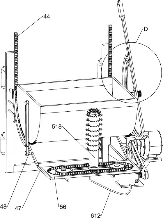
[0030] A feeding trough for livestock with cleaning function, such as Figure 1-8 As shown, it includes a mounting frame 1, a connecting fixed rod 2, a feeding trough 3, a turning mechanism 4 and a scrubbing mechanism 5. The front and rear sides of the upper left side of the mounting frame 1 are connected with a connecting fixed rod 2, and the connecting fixed rod 2 is installed Turning mechanism 4 is arranged, and feeding trough 3 is installed on the turning mechanism 4, and scrubbing mechanism 5 is installed between mounting frame 1 and turning mechanism 4.
[0031] Turnover mechanism 4 includes housing rack 41, first fixed mount 42, first gear 43, sliding rack 44, limit frame 45, first connecting rod 46, second fixed mount 47 and first rotating shaft 48, feeding trough 3. The front and rear sides of the outer wall are connected with a housing rack 41, connected with a limit frame 45 on the fixed rod 2, and a sliding rack 44 is slidably connected in the limit frame 45, and t...
Embodiment 2
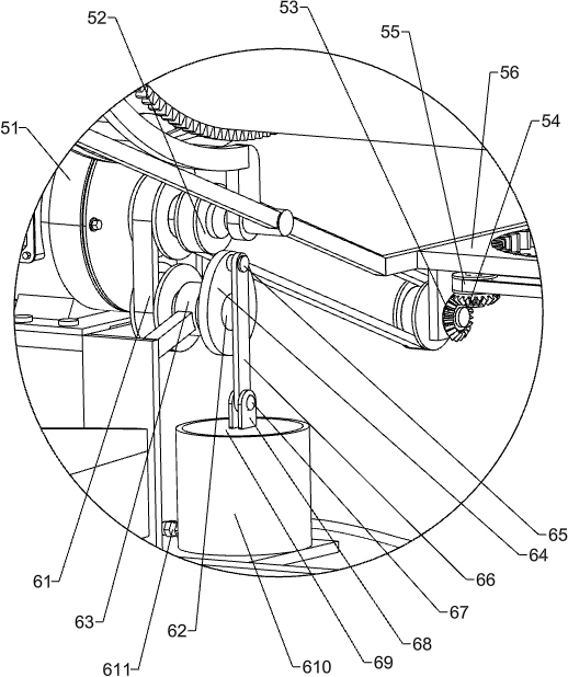
[0035] On the basis of Example 1, such as figure 1 , Figure 4 , Figure 7 and Figure 8 As shown, a flushing mechanism 6 is also included, and the flushing mechanism 6 includes a third transmission belt set 61, a first connecting shaft 62, a fixed ring frame 63, a cam 64, a second connecting shaft 65, a sliding link 66, a third connecting Shaft 67, connecting block 68, piston 69, compression barrel 610, water inlet check valve 611, pressurized water pipe 612, sliding collar 613, hard water delivery pipe 614 and perforated collar 615, the rear part of the bracket is connected with a fixed ring frame 63, the first connecting shaft 62 is connected with the rotation type in the fixed ring frame 63, the third transmission belt group 61 is connected between the front end of the first connecting shaft 62 and the output shaft of the servo motor 51, and the rear end of the first connecting shaft 62 is connected with Cam 64, on the eccentric position of cam 64 rear side, the second ...
Embodiment 3
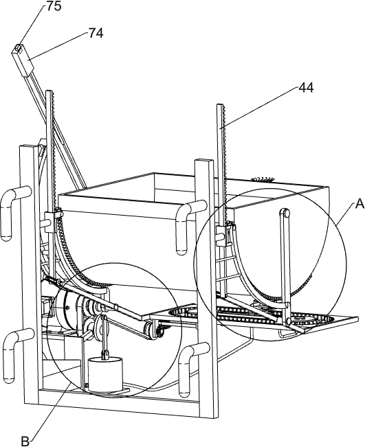
[0038] On the basis of Example 2, such as Figure 1-3 and Figure 9-10 As shown, also includes fixing mechanism 7, and fixing mechanism 7 includes grooved guide rail frame 71, the 3rd connecting rod 72, position-limiting long bar 73, handle 74, button 75, position-limiting fixing ring 76, back-moving spring 77, The second limit ring 78, the long connecting rod 79, the wedge block 710, the limit tube 711 and the second rotating shaft 712, and the front side of the first fixed mount 42 on the front side are connected with a plurality of third connecting rods 72 evenly spaced. A slotted guide rail frame 71 is connected between the front ends of the third connecting rods 72, a second rotating shaft 712 is connected to the front side of the feeding trough 3, and a limit rod 73 is connected on the second rotating shaft 712, and the limit rod 73 bottom is sliding. Connected in the slotted guide rail frame 71, the top of the limit rod 73 is connected with a handle 74, the handle 74 i...
PUM
 Abstract
Description
Claims
Application Information
 - R&D
- Intellectual Property
- Life Sciences
- Materials
- Tech Scout
- Unparalleled Data Quality
- Higher Quality Content
- 60% Fewer Hallucinations
Browse by: Latest US Patents, China's latest patents, Technical Efficacy Thesaurus, Application Domain, Technology Topic, Popular Technical Reports.
© 2025 PatSnap. All rights reserved.Legal|Privacy policy|Modern Slavery Act Transparency Statement|Sitemap|About US| Contact US: help@patsnap.com