Discharging device for mechanical equipment

A technology for mechanical equipment and material cutting, applied in the field of mechanical equipment, can solve the problems of inconvenient material dredging, unfavorable equipment, material residue, etc., and achieve the effect of preventing excessive workload, rational design of structure and principle, and improving service life.

Inactive Publication Date: 2020-09-25
孟正明
View PDF1 Cites 3 Cited by
  • Summary
  • Abstract
  • Description
  • Claims
  • Application Information

AI Technical Summary

Problems solved by technology

[0002] Architecture is the general term for buildings and structures. It is an artificial environment created by people using material and technical means and certain scientific and aesthetic laws to meet the needs of social life. In the process of building construction, specific machinery is required. Equipment for mixing sand and gravel, such as cement mixers, when large cement mixers are in use, a large amount of cement and other materials need to be dumped into the mixer, but due to the large amount of materials, different types and shapes of materials, and different humidity, etc., these The material is easy to block in the feed port, but the ordinary cement mixer is not convenient to dredge the material, so that the material is always blocked in the feed port, which is not conducive to the equipment unloading, and it is easy to solidify in the feed port, which will affect the normal operation of the equipment. not conducive to the use of
[0003] In the Chinese invention patent document with the publication number CN108927900A, a cutting device for mechanical equipment is disclosed. The device drives the cam to rotate through the motor, and then the pestle rod drives the pushing plate to push the material repeatedly, so that the blocked material It can be dredged, but in actual use, although the movement of the pusher plate can realize the dredging of the channel, the movement of the pusher plate will also drive the material to move up and down. On the one hand, it reduces the falling speed of the material. On the other hand, some materials It will be brought back into the storage box by the pushing plate, resulting in material residue in the storage box, and the device cannot achieve uniform quantitative feeding. In actual use, if too much material is manually added to the feeding box , although it can be dredged through the pusher plate, when the material falls into the feeding box, it will increase the workload of the conveying device, so that the conveying device cannot achieve uniform feeding, affecting the actual use effect

Method used


Image

  • Discharging device for mechanical equipment
  • Discharging device for mechanical equipment
  • Discharging device for mechanical equipment

Examples


Embodiment 1

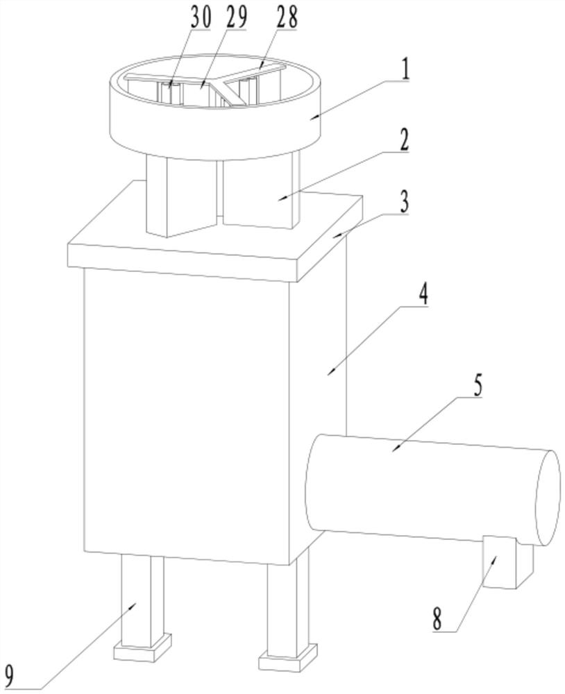
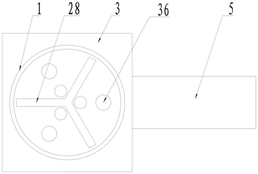
[0025] see Figure 1-7 , a blanking device for mechanical equipment, comprising a collection tank 1, the installation column 27 is rotatably connected in the collection tank 1, and the bottom of the collection tank 1 on the axial side of the installation column 27 is fixedly connected to the first motor 37, the first The output shaft of a motor 37 is fixedly connected to the mounting column 27, and the top side of the mounting column 27 is fixedly connected to the bearing rod 28 at equal intervals, and the two sides of the bottom of the bearing rod 28 are fixedly connected to the scraper 29, and the bearing rod 28 between the scraper 29 The bottom is rotatably connected to the rotating roller 30, and there are two rotating rollers 30. The bottom of the collecting tank 1 is provided with a feeding hole 36, which corresponds to the bottom of the scraper 29 on both sides of the bottom of the carrying rod 28, and the bottom of the feeding hole 36. The bottom of the collection tank...

Embodiment 2

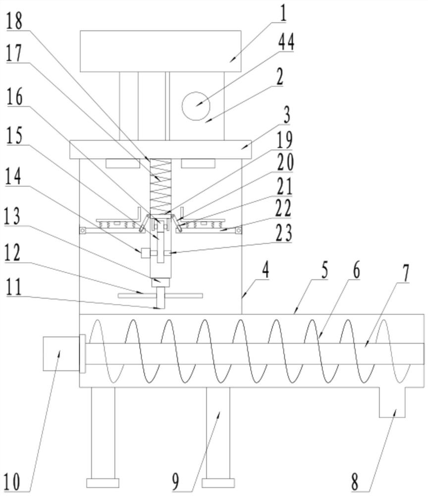
[0031] see Figure 1-7 , the other content of this embodiment is the same as that of Embodiment 1, the difference is that: the rotating column 38 between the stirring blades 43 is fixedly connected to the stirring drum 39 at equal arc intervals, and the fourth spring 42 is fixedly connected to the stirring drum 39, The bottom of the fourth spring 42 is fixedly connected to the stirring column 40 , one side of the stirring column 40 passes through the mixing drum 39 , and the end is fixedly connected to the cleaning block 41 .

[0032] During the implementation of the present invention, by adding materials to be used in the collecting tank 1, driven by the first motor 37, the bearing rod 28 on the mounting column 27 drives the scraper 29 to move, and at the same time, the fifth motor 32 drives the rotation The roller 30 rotates, and the two rotating rollers 30 rotate in the opposite direction under the action of the transmission gear 31, conveying the material between the two s...


PUM


Abstract

The invention discloses a discharging device for mechanical equipment, and relates to the technical field of mechanical equipment. The discharging device includes a collecting tank, a mounting columnis connected with the collecting tank in a rotating mode, a first motor is fixedly connected with the bottom of the collecting tank on one axial side of the mounting column, bearing rods are fixedly connected with one side of the top end of the mounting column at equal intervals, scrapers are fixedly connected with two sides of the bottom of the bearing rods, and two rotating rollers are connectedwith the bottom of the bearing rods between the scrapers in a rotating mode. Feeding holes are opened at the bottom of the collecting tank and corresponds to the lower parts of the scrapers on two sides of the bottom of the bearing rods respectively, a sending shell is fixedly connected with the bottom of the collecting tank below the feeding holes, a mounting plate is fixedly connected with thebottom of the sending shell, a mounting box is fixedly connected with the bottom of the mounting plate, a sending drum is fixedly connected with the bottom of the mounting tank, a transmission columnis connected with the sending drum in a rotating mode, a second motor is fixedly connected with an outside wall of the sending drum on one axial side of the transmission column, and a spiral sending blade is fixedly connected with the transmission column. The device is reasonable in structural principle design, convenient for operation and use, and high in practicability.

Description

technical field [0001] The invention relates to the technical field of mechanical equipment, in particular to a cutting device for mechanical equipment. Background technique [0002] Architecture is the general term for buildings and structures. It is an artificial environment created by people using material and technical means and certain scientific and aesthetic laws to meet the needs of social life. In the process of building construction, specific machinery is required. Equipment for mixing sand and gravel, such as cement mixers, when large cement mixers are in use, a large amount of cement and other materials need to be dumped into the mixer, but due to the large amount of materials, different types and shapes of materials, and different humidity, etc., these The material is easy to block in the feed port, but the ordinary cement mixer is not convenient to dredge the material, so that the material is always blocked in the feed port, which is not conducive to the equipm...

Claims


Application Information

Patent Timeline
Patent Type & Authority Applications(China)
IPC IPC(8): B65G65/32B65G65/46B65D88/64B65D88/68B65D90/00
CPCB65D88/64B65D88/68B65D90/0093B65G65/32B65G65/46
Inventor 胡嘉侃孟正明
Owner 孟正明
Why Eureka
Try Eureka