Wear-resistant efficient horizontal centrifugal sand pump and working method thereof

A wear-resistant and high-efficiency technology, applied in the field of centrifugal pumps, can solve the problems of low safety performance, high viscosity of the conveying fluid, poor conveying effect, etc., and achieve the effect of increasing the response to serious leakage, high equipment circulation speed, and not easy to leak to the outside world.

Active Publication Date: 2020-03-31
新沂市利源机械有限公司
View PDF4 Cites 3 Cited by
  • Summary
  • Abstract
  • Description
  • Claims
  • Application Information

AI Technical Summary

Problems solved by technology

[0005] 1. Due to the high viscosity of the conveying fluid, the current sand pump is prone to sticking and clogging, resulting in equipment failure and poor conveying effect
[0006] 2. Most of the current sand pumps adopt the traditional bolt and gasket sealing method, and the sealing effect is not high
[0007] 3. Most of the current sand pumps do not have the detection and response to leakage, poor practicability and low safety performance

Method used


Image

  • Wear-resistant efficient horizontal centrifugal sand pump and working method thereof
  • Wear-resistant efficient horizontal centrifugal sand pump and working method thereof
  • Wear-resistant efficient horizontal centrifugal sand pump and working method thereof

Examples


Embodiment 1

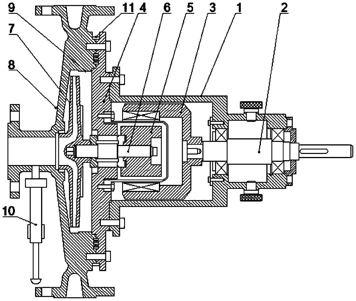
[0037] Such as figure 1 A wear-resistant high-efficiency horizontal centrifugal sand pump shown includes: pump casing 1, motor shaft 2, outer magnetic rotor 3, spacer sleeve 4, inner magnetic rotor 5, linkage shaft 6, impeller 7, end cover 8 and Wear-resistant layer 9, the pump casing 1 is provided with a motor shaft 2, one end of the motor shaft 2 is connected with an outer magnetic rotor 3, and the outer magnetic rotor 3 is arranged in the pump casing 1, and the outer magnetic rotor 3 A spacer 4 is arranged inside, and the spacer 4 is fixedly connected with the pump casing 1. An inner magnetic rotor 5 is arranged inside the spacer 4. One end of the inner magnetic rotor 5 is connected with a linkage shaft 6. The linkage shaft 6. An impeller 7 is provided at one end away from the inner magnetic rotor 3. An end cover 8 is provided outside the impeller 7. The end cover 8 is fixedly connected to the spacer sleeve 4. A gap is provided between the end cover 8 and the spacer sleeve ...

Embodiment 2

[0052] Such as figure 1 A wear-resistant high-efficiency horizontal centrifugal sand pump shown includes: pump casing 1, motor shaft 2, outer magnetic rotor 3, spacer sleeve 4, inner magnetic rotor 5, linkage shaft 6, impeller 7, end cover 8 and Wear-resistant layer 9, the pump casing 1 is provided with a motor shaft 2, one end of the motor shaft 2 is connected with an outer magnetic rotor 3, and the outer magnetic rotor 3 is arranged in the pump casing 1, and the outer magnetic rotor 3 A spacer 4 is arranged inside, and the spacer 4 is fixedly connected with the pump casing 1. An inner magnetic rotor 5 is arranged inside the spacer 4. One end of the inner magnetic rotor 5 is connected with a linkage shaft 6. The linkage shaft 6. An impeller 7 is provided at one end away from the inner magnetic rotor 3. An end cover 8 is provided outside the impeller 7. The end cover 8 is fixedly connected to the spacer sleeve 4. A gap is provided between the end cover 8 and the spacer sleeve ...

Embodiment 3

[0054] Such as figure 1 A wear-resistant high-efficiency horizontal centrifugal sand pump shown includes: pump casing 1, motor shaft 2, outer magnetic rotor 3, spacer sleeve 4, inner magnetic rotor 5, linkage shaft 6, impeller 7, end cover 8 and Wear-resistant layer 9, the pump casing 1 is provided with a motor shaft 2, one end of the motor shaft 2 is connected with an outer magnetic rotor 3, and the outer magnetic rotor 3 is arranged in the pump casing 1, and the outer magnetic rotor 3 A spacer 4 is arranged inside, and the spacer 4 is fixedly connected with the pump casing 1. An inner magnetic rotor 5 is arranged inside the spacer 4. One end of the inner magnetic rotor 5 is connected with a linkage shaft 6. The linkage shaft 6. An impeller 7 is provided at one end away from the inner magnetic rotor 3. An end cover 8 is provided outside the impeller 7. The end cover 8 is fixedly connected to the spacer sleeve 4. A gap is provided between the end cover 8 and the spacer sleeve ...


PUM


Abstract

The invention discloses a wear-resistant efficient horizontal centrifugal sand pump. The wear-resistant efficient horizontal centrifugal sand pump comprises a pump housing, a motor shaft, an outer magnetic rotor, an isolation sleeve, an inner magnetic rotor, a linkage shaft, an impeller, an end cover and a wear-resistant layer, wherein the motor shaft is arranged inside the pump housing; one end of the motor shaft is connected with the outer magnetic rotor; the isolation sleeve is arranged inside the outer magnetic rotor; the inner magnetic rotor is arranged inside the isolation sleeve; one end of theinner magnetic rotor is connected with the linkage shaft; the impeller is arranged at one end of the linkage shaft; the end cover is arranged on the outer side of the impeller; the wear-resistant layer is arranged on the surface of a cavity between the end cover and the isolation sleeve; and the wear-resistant efficient horizontal centrifugal sand pump further comprises a dredging mechanism and a sealing mechanism. The invention further discloses a working method of the wear-resistant efficient horizontal centrifugal sand pump. On one hand, the space in the pump can be dredged, the problem of blockage in the pump is effectively solved, the circulation speed of equipment is high, and the effect is good; and on the other hand, multiple sealing and leakage detection are adopted, so that the problems that the equipment is poor in sealing and easy to leak are solved.

Description

technical field [0001] The invention belongs to the field of centrifugal pumps, in particular to a wear-resistant high-efficiency horizontal centrifugal sand pump and its working method. Background technique [0002] The centrifugal sand pump is mainly used to support the circulating solid control system of the oil field drilling rig, and its function is to provide drilling fluid with a certain displacement and pressure for the desander, desilter, mixer, etc., so as to ensure the efficient operation of these equipment . Since the emergence of centrifugal pumps in the 1930s and 1940s, they have been in continuous development and have been in a state of great demand in the market. Nowadays, there are more than 600 pump manufacturing enterprises in my country, with an annual output value of nearly 20 billion, which is still rising. It can be seen that the centrifugal sand pump is an indispensable equipment in modern industrial production. [0003] However, due to the huge ma...

Claims


Application Information

Patent Timeline
Patent Type & Authority Applications(China)
IPC IPC(8): F04D7/04F04D13/06F04D13/02F04D29/16F04D15/00F04D29/42F04D29/22
CPCF04D7/045F04D13/024F04D13/06F04D15/0077F04D29/167F04D29/2222F04D29/426F04D29/4293
Inventor 袁珩博
Owner 新沂市利源机械有限公司
Why Eureka
Try Eureka