Rewinding edge thread head shearing machinery for processing
A sideline head and mechanical technology, applied in the field of fabric processing, can solve the problems of heavy workload, easy cutting of fabric, loss, etc.
- Summary
- Abstract
- Description
- Claims
- Application Information
AI Technical Summary
Problems solved by technology
Method used
Image
Examples
Embodiment 1
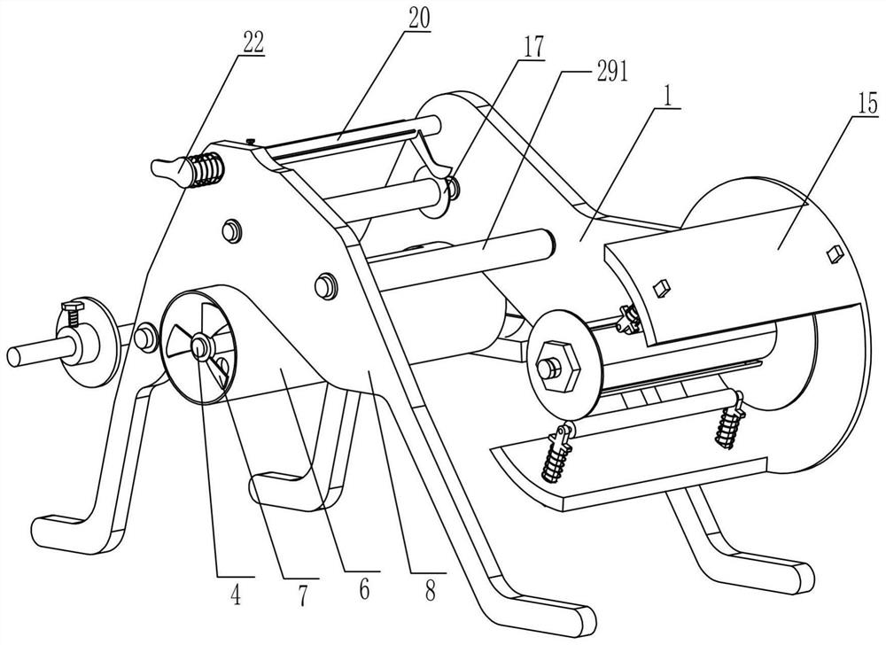
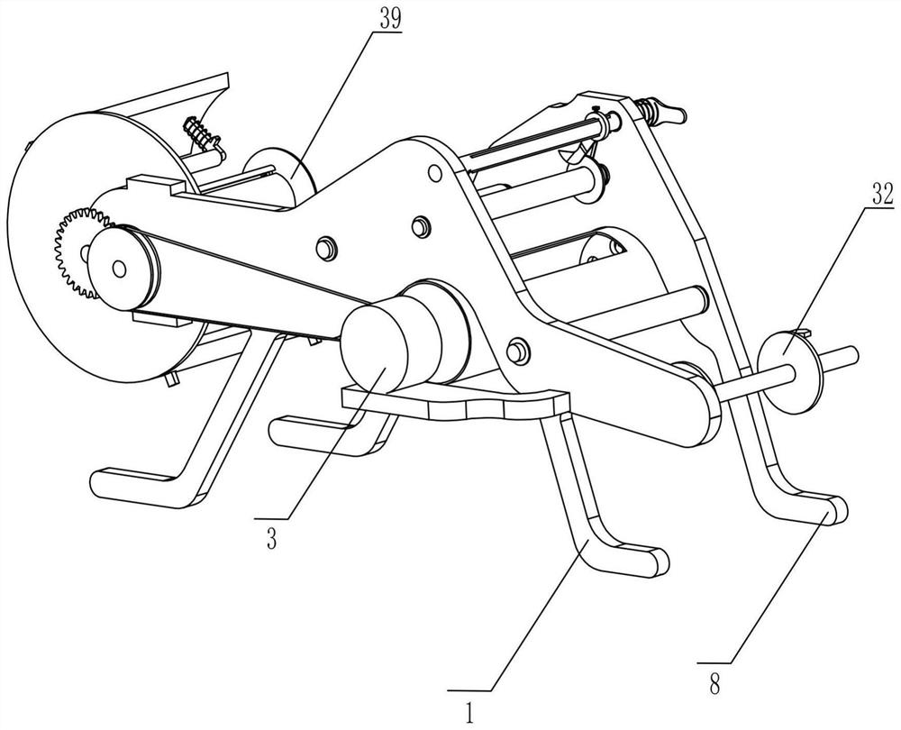
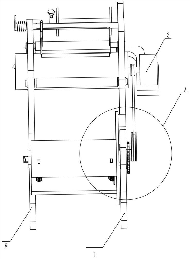
[0024] Such as Figure 1-8 As shown, a rewinding edge thread cutting machine for processing includes a support seat 1, a supporting plate 2, a motor 3, a rotating shaft 4, a first pulley 5, an air suction cylinder 6, fan blades 7, and a support seat Two 8, rotating shaft two 9, second pulley 10, belt 11, gear one 12, rotating shaft three 13, gear two 14, mounting plate 15 and shear mechanism, and the supporting plate 2 is fixedly installed on the rear side of support seat one 1 , the motor 3 is fixedly installed on the supporting plate 2 and is close to the support base 1, the rear end of the rotating shaft 4 is fixedly connected to the output end of the motor 3, and the first pulley 5 is fixedly installed on the rotating shaft 4 and close to The motor 3, the suction tube 6 with the gap is fixedly installed on the lower side of the support seat one 1, the fan blade 7 is fixedly mounted on the front end of the rotating shaft one 4 and is located in the suction tube 6, and the f...
Embodiment 2
[0030] On the basis of Example 1, such as Figure 1-8 As shown, in the process of rewinding the cloth, the pressing mechanism capable of pressing the cloth so that it does not wrinkle includes a spring two 37, a clamp block 38, a sliding chuck three 39, a nut 40, a telescopic rod 41, a movable Wheel 42 and spring three 43, one end of four springs two 37 is fixedly mounted on the inner side of roller three 35, two clamp blocks 38 are fixedly mounted on the other end of spring two 37, and the sliding chuck three 39 of the adjustable position slides installed on the rotating shaft 3 13 and located in front of the roller 3 35, the nut 40 is sleeved on the rotating shaft 13 and located on the front side of the sliding chuck 39, manually turning the nut 40 can adjust the position of the sliding chuck 39, four Described telescoping rod 41 is divided into two groups and is slidably installed on the mounting plate 15 and is arranged symmetrically, and two described movable wheels 42 th...
PUM
 Abstract
Description
Claims
Application Information
 - R&D
- Intellectual Property
- Life Sciences
- Materials
- Tech Scout
- Unparalleled Data Quality
- Higher Quality Content
- 60% Fewer Hallucinations
Browse by: Latest US Patents, China's latest patents, Technical Efficacy Thesaurus, Application Domain, Technology Topic, Popular Technical Reports.
© 2025 PatSnap. All rights reserved.Legal|Privacy policy|Modern Slavery Act Transparency Statement|Sitemap|About US| Contact US: help@patsnap.com


