
Nuclear radiation resistant mobile cable for crown block

A nuclear radiation-resistant and mobile cable technology, which is applied in the field of cables, can solve the problems that easily affect the erection of construction supports, the large footprint of flat cables, and affect the safety of use, so as to achieve a small footprint, reduce the impact of erection, and alleviate wear effect

Active Publication Date: 2020-09-25
ANHUI DUJIANG CABLE GROUP
View PDF8 Cites 0 Cited by
  • Summary
  • Abstract
  • Description
  • Claims
  • Application Information

AI Technical Summary

Problems solved by technology

When the round cable is used to connect the bridge frame and the lifting trolley, it is easy to be entangled, which affects the safety of use. Therefore, in the prior art, flat cables are generally used as the dragging cables of the crane. The flat cable occupies a large area, which is easy to affect the erection of the construction support; and the friction surface is large, and it is easy to wear after long-term use, so it needs to be improved

Method used


Image

  • Nuclear radiation resistant mobile cable for crown block
  • Nuclear radiation resistant mobile cable for crown block
  • Nuclear radiation resistant mobile cable for crown block

Examples


Embodiment 1

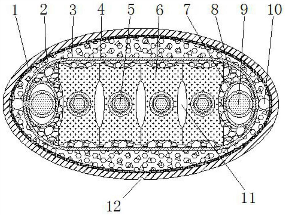
[0028] like figure 1 A nuclear radiation-resistant mobile cable for cranes shown includes a cable core, an insulating layer 4 wrapped outside the cable core, an armor layer 2 arranged outside the insulating layer 4, and an armor layer wrapped outside the armor layer 2. Sheath layer 1, the cable core includes a main core 5 and a ground core 9;

[0029] The cross-sections of the armor layer 2 and the sheath layer 1 are both oval, the sheath layer 1 is made of irradiated cross-linked polyethylene material, and the outer surface of the sheath layer 1 is provided with a A wear-resistant groove 12 extending in the length direction, and the groove surface in the wear-resistant groove 12 is sprayed with wear-resistant paint; the armor layer 2 is a sleeve-like structure formed by braiding copper tape;

[0030] The cross-section of the insulating layer 4 is flat, and its two sides are in a convex arc shape. The insulating layer 4 is an insulating layer of irradiated cross-linked polyet...

Embodiment 2

[0035] The difference between this embodiment and embodiment 1 is:

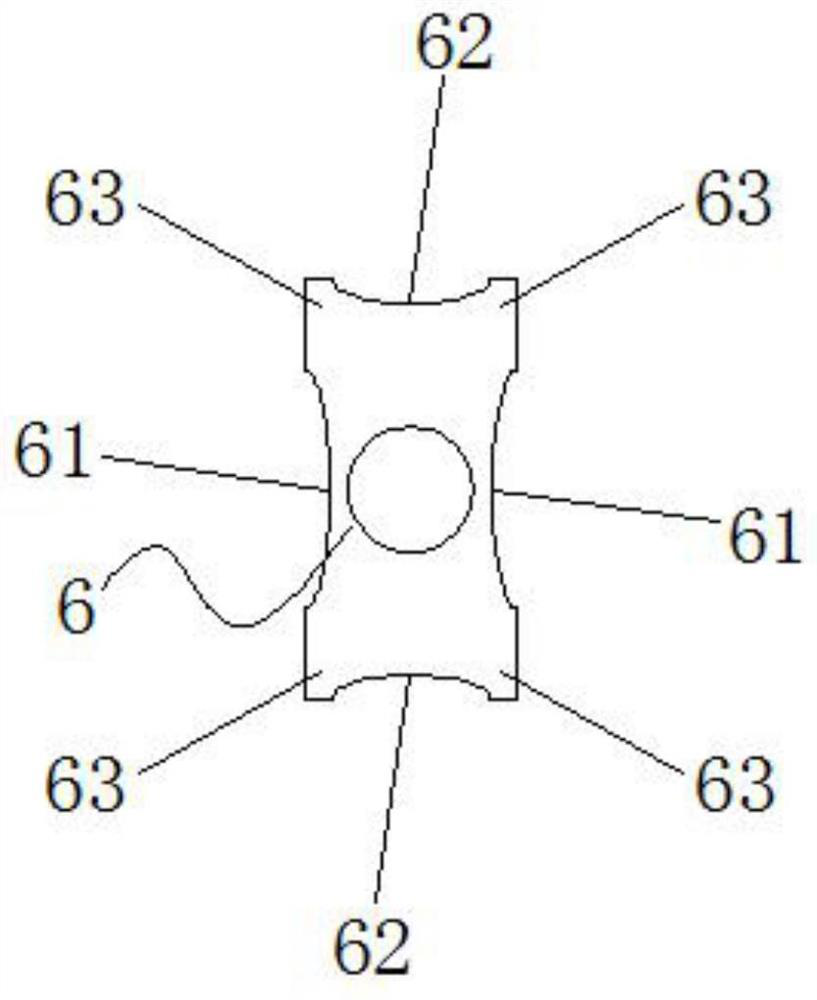
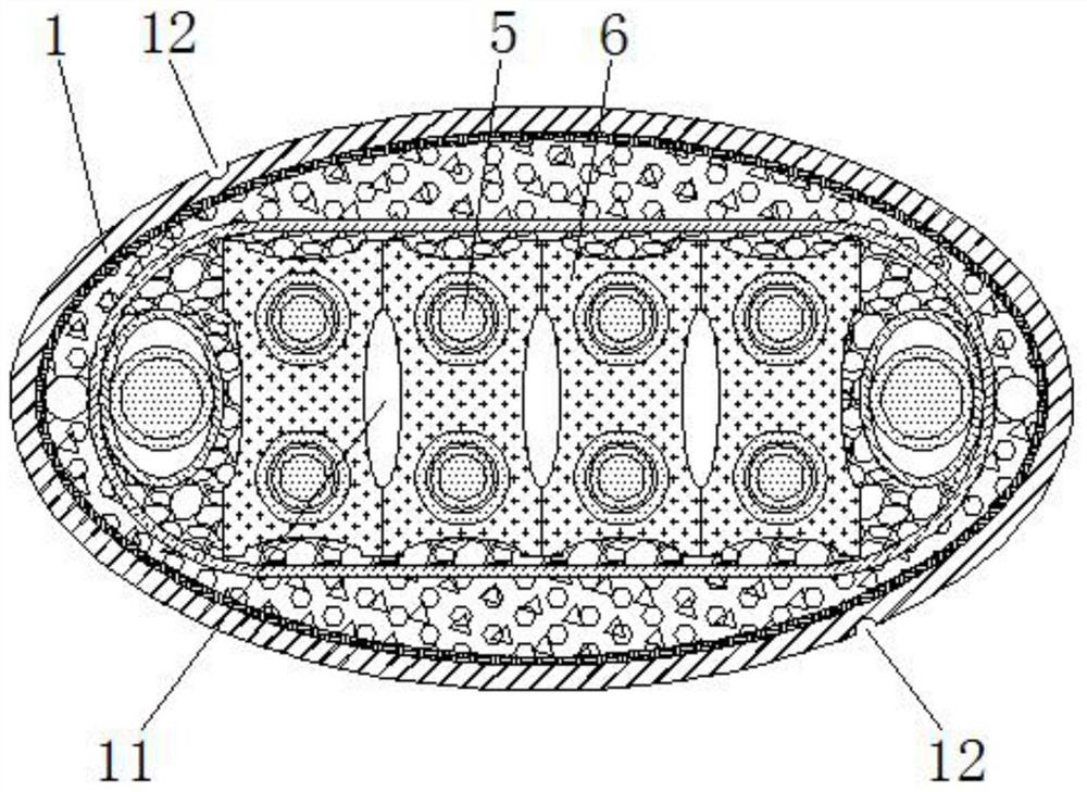
[0036] In this example, if image 3 As shown, the cable core is provided with a row of first protective sheaths 6 attached one by one, and each first protective sheath 6 is provided with two main cores 5 on the inner side, and each adjacent two first protective sheaths 6 face each other. The first arc-shaped grooves 61 on the side are pieced together to form an oval cavity 11 . The arrangement of more main wire cores 5 can be realized.

[0037] In this example, if image 3 As shown, the outer surface of the sheath layer 1 is provided with two wear-resistant grooves 12 extending along its length direction, and the two wear-resistant grooves 12 are symmetrical with respect to the cross-sectional center of the cable.

[0038] Others are the same as embodiment 1.

Embodiment 3

[0040] The difference between this embodiment and embodiment 1 is:

[0041] In this example, if Figure 4 and Figure 5 As shown, the cable core is provided with two rows of first protective sheaths 6 attached one by one, and the bottom of the first protective sheath 6 of the last row is attached to the top of the first protective sheath 6 of the next row, The inner side of each first protective cover 6 is provided with a main wire core 5, and the first arc-shaped grooves 61 on the opposite sides of each adjacent two first protective covers 6 are pieced together to form an oval cavity 11, and each adjacent two The second arc-shaped grooves 62 on opposite sides of the first protective sleeve 6 form an oval cavity 11. The arrangement of more main cores 5 can be realized, and the number of cavities 11 can be increased, thereby improving the flexibility of the cable.

[0042] In this example, if Figure 4 As shown, the outer surface of the sheath layer 1 is provided with four ...


PUM


Abstract

The invention discloses a nuclear radiation resistant mobile cable for a crown block, and belongs to the technical field of cables. The cable comprises a cable core, an insulating layer, an armor layer and a sheath layer. The cross section of the sheath layer is elliptical, the outer side surface of the sheath layer is provided with a wear-resistant groove, the sheath layer is an irradiation crosslinked polyethylene outer sheath, and a crosslinked polytetrafluoroethylene material, a flame-retardant material and an elastic material are filled between the armor layer and the insulating layer. The cable core in a flat shape, and a first protective sleeve and a second protective layer are arranged in the protective sleeve. The cross section of each first protective sleeve is square, the innerside of each first protective sleeve is provided with a main wire core, each first protective sleeve is provided with a first arc-shaped groove and a second arc-shaped groove, the opposite sides of every two adjacent first protective sleeves are spliced to form a cavity, the cross section of the second protective layer is oval, and a ground wire core is arranged in the second protective layer. Thecable is good in nuclear radiation resistance, flame retardance and stamping resistance, good in flexibility, capable of preventing the cables from rolling and winding each other during dragging andcapable of relieving abrasion caused by long-time use.

Description

technical field [0001] The invention relates to the technical field of cables, in particular to a nuclear radiation-resistant mobile cable for a crane. Background technique [0002] In recent years, the rapid development of domestic nuclear power has attracted great attention from the supporting wire and cable industry. Nuclear power plant cables need to have better radiation resistance to ensure the operation stability of nuclear power plants. In the actual working conditions of nuclear power plants, because the crane is constantly moving, the cables need to be able to drag, bend and rub at will. The cables for the crane must be able to withstand the needs of high tensile and high wear resistance. When the round cable is used to connect the bridge frame and the lifting trolley, it is easy to be entangled, which affects the safety of use. Therefore, in the prior art, flat cables are generally used as the dragging cables of the crane. The flat cable occupies a large area, wh...

Claims


Application Information

Patent Timeline
Patent Type & Authority Applications(China)
IPC IPC(8): H01B7/08H01B7/18H01B7/295H01B7/17H01B7/40H01B3/44H01B7/04
CPCH01B7/08H01B7/184H01B7/1805H01B7/1875H01B7/17H01B7/295H01B7/40H01B3/44H01B7/04
Inventor 巫春生徐志敏毕亮亮胡宏生万长东张家文
Owner ANHUI DUJIANG CABLE GROUP
Learn More