Wall thickness error precision control machining device and method for rotating shell parts

A precise control and processing device technology, applied in the direction of automatic control device, workpiece feed movement control, feeding device, etc., can solve problems such as difficult to meet high contour accuracy and high wall thickness error, low adjustment efficiency, high technical requirements, etc., to achieve Quantification, improvement of contour accuracy and wall thickness error, easy to use and simple effects

Active Publication Date: 2020-09-29
DALIAN UNIV OF TECH
View PDF11 Cites 10 Cited by
  • Summary
  • Abstract
  • Description
  • Claims
  • Application Information

AI Technical Summary

Problems solved by technology

Therefore, the height of the tool tip and the alignment error of the secondary clamping of the part have become the bottleneck that restricts the improvement of the contour accuracy and wall thickness error of the part, which makes it difficult to meet the requirements of high contour accuracy and high wall thickness error after machining such parts
[0004] At present, the height adjustment of the tool tip mainly uses an optical tool setting instrument for semi-fine adjustment of the tool tip height, and then uses the method of trial cutting combined with a high-power magnifying glass to observe the center shape of the workpiece to fine-tune the height of the tool tip. During the adjustment process of the trial cutting method Repeated trial cutting-measurement-adjustment is required, the process is complex, time-consuming and laborious, and the adjustment efficiency is low. It is difficult to meet the actual processing requirements when the tool angle and the height...

Method used


Image

  • Wall thickness error precision control machining device and method for rotating shell parts
  • Wall thickness error precision control machining device and method for rotating shell parts
  • Wall thickness error precision control machining device and method for rotating shell parts

Examples


Embodiment Construction

[0049] The present invention will be described in detail below in conjunction with the accompanying drawings.

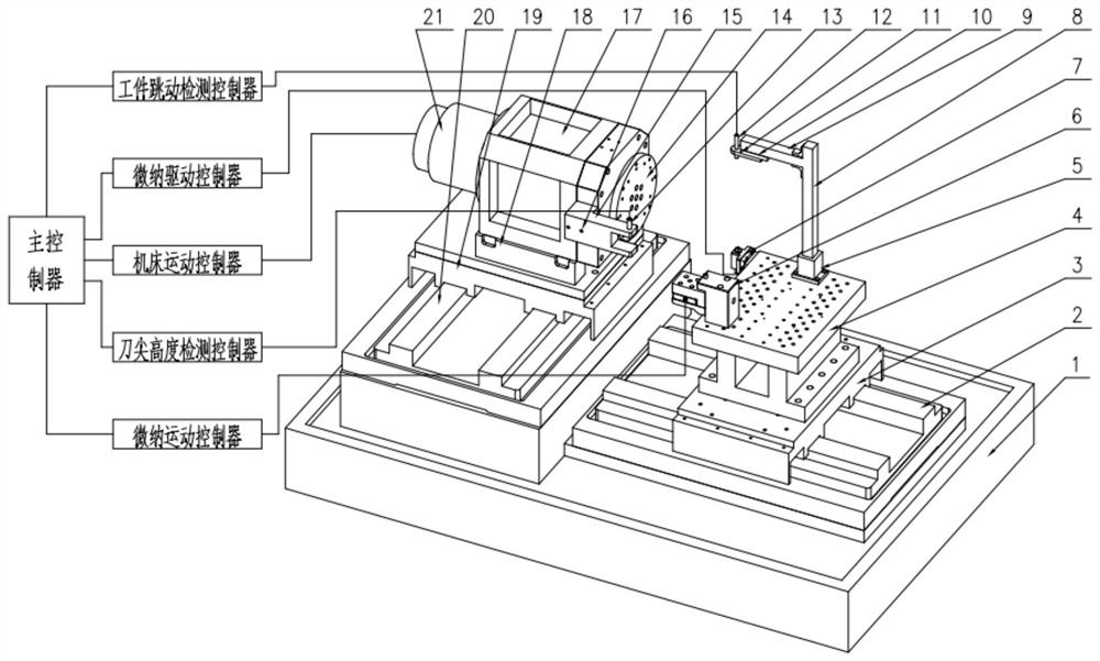
[0050] Such as Figure 1-11 As shown, the precise control processing device for the wall thickness error of the rotary shell parts includes the main controller, the machine tool motion controller, the workpiece runout precision detection device, the workpiece position precision adjustment device 7, the tool tip height precision detection device, and the tool tip height precision adjustment device 6 , and its subsidiary structure, said subsidiary structure comprises bed 1, Z-axis guide rail 2, Z-axis support plate 3, marble seat 4, main shaft (C-axis) seat 17, main shaft (C-axis) cushion 18, X-axis Pallet 19, X-axis guide rail 20, main shaft (C-axis) 21.

[0051] The workpiece jumping precision detection device includes a workpiece jumping detection controller, a jumping detection device base 5, a jumping detection device column 8, a jumping detection device crossbea...


PUM


Abstract

The invention provides a wall thickness error precision control machining device and method for rotating shell parts, and belongs to the field of precision/ultra-precision machining. The machining device comprises a main controller, a workpiece runout precision detection device, a workpiece position precision adjustment device, a tool tip height precision detection device, a tool tip height precision adjustment device and an auxiliary structure. The workpiece runout precision detection device is used for precisely detecting runout of parts. The workpiece position precision adjustment device isused to achieve accurate and fast alignment of workpieces. The tool tip height precision detection device comprises a tool tip height detection controller and a tool tip height detection sensor, andis used for precisely checking tool tip heights. The tool tip height precision adjustment device comprises a micro-nano motion controller, a tool holder base, a dovetail guide rail, upper and lower tool rest blocks, and a micro-nano lifting platform. The tool tip height precision adjustment device is used to adjust the tool tip height at micro-nano precision. The machining device and method are simple. The machining device can meet the machining requirements of high profile precision and low wall thickness error of rotary parts, and automation is easy to realize.

Description

technical field [0001] The invention belongs to the field of precision / ultra-precision machining, and in particular relates to a machining device and method for precisely controlling wall thickness errors of rotary shell parts. Background technique [0002] Rings, shafts, bushings, spherical or aspherical parts, casings and other high-precision rotary parts are widely used in aerospace, military, medical, precision instruments and precision physical experiments and other fields. In order to meet the special requirements of specific fields, The contour accuracy and wall thickness error of this type of rotary parts have extremely high processing requirements. Ultra-precision grinding and other methods for processing. [0003] For this kind of rotary parts that need to be turned over to meet the extremely high requirements of the inner and outer surface contour accuracy and wall thickness error of the part, when ultra-precision turning or ultra-precision grinding, first, the t...

Claims


Application Information

Patent Timeline
IPC IPC(8): B23Q15/22B23Q17/00B23Q17/22B24B49/00B24B49/10B24B49/12
CPCB23Q15/22B23Q17/00B23Q17/2266B23Q2017/001B24B49/00B24B49/10B24B49/12
Inventor 康仁科郭江刘光宇焦振华
Owner DALIAN UNIV OF TECH
Why Eureka
Try Eureka