
Position detection system and method and maglev transmission device

A technology of conveying device and detection system, applied in the field of position detection system and maglev conveying device, can solve the problems of inability to detect the position and speed of the motor mover in real time, low precision, and large maintenance amount.

Active Publication Date: 2020-09-29
湖南凌翔磁浮科技有限责任公司
View PDF7 Cites 1 Cited by
  • Summary
  • Abstract
  • Description
  • Claims
  • Application Information

AI Technical Summary

Problems solved by technology

[0002] At present, major enterprises and factories widely use mechanical conveyor belts or mechanical linear motors on the production line to transport items. The principle of mechanical conveyor belts is to drive belts or chain plates to move through rotating motors. The converter is converted into linear kinetic energy to drive the mover movement. Due to the inevitable existence of mechanical friction, the mechanical conveyor belt or mechanical linear motor has low efficiency, high noise, easy damage to friction parts, large follow-up maintenance, and low positioning accuracy during transportation. And other problems, and the mover part of the mechanical linear motor also needs to be connected to the cable, and the flexibility will be affected by the constraints of the cable during movement.
[0003] At present, some companies on the market have designed a magnetic levitation conveyor belt that uses permanent magnet linear motors to transport goods. However, the control system of conventional mechanical conveyor belts cannot detect the position and speed of the motor mover on the track in real time, so that the transportation process cannot be realized. Precise scheduling and control in

Method used


Image

  • Position detection system and method and maglev transmission device
  • Position detection system and method and maglev transmission device
  • Position detection system and method and maglev transmission device

Examples


Embodiment Construction

[0035] Embodiments of the present invention are described in detail below, examples of which are shown in the drawings, wherein the same or similar reference numerals designate the same or similar elements or elements having the same or similar functions throughout. The embodiments described below by referring to the figures are exemplary only for explaining the present invention and should not be construed as limiting the present invention.

[0036] In the description of the invention, multiple means one or more, and multiple means two or more. Greater than, less than, exceeding, etc. are understood as not including the original number, and above, below, within, etc. are understood as including the original number. If the description of the first and second is only for the purpose of distinguishing the technical features, it cannot be understood as indicating or implying the relative importance or implicitly indicating the number of the indicated technical features or implicit...


PUM


Abstract

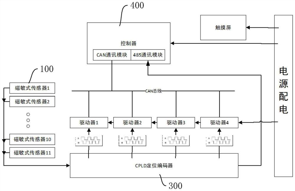
The invention discloses a position detection system and a maglev transmission device. The position detection system comprises a magnetic grating ruler, multiple magnetically-sensitive sensors, a CPLDpositioning encoder and a controller, wherein the magnetic grating ruler is arranged on a promotor of the maglev transmission device; the magnetically-sensitive sensors are uniformly distributed alonga track of the maglev transmission device to be used for inducting the magnetic grating ruler, and the mounting spacing between every two adjacent magnetically-sensitive sensors is smaller than the length of the magnetic grating ruler; the magnetically-sensitive sensors are connected with the CPLD positioning encoder, and the CPLD positioning encoder integrates sensor information into pulse signals; and the controller is connected with the CPLD positioning encoder. A position detection method of the maglev transmission device is further included. According to the method, the CPLD positioningencoder firstly performs clock synchronization on the pulse signals fed back by the magnetically-sensitive sensors, then integrates the pulse signals of the magnetically-sensitive sensors into one channel and feeds back the channel to the controller, and the controller calculates the motion distance and direction of the promotor according to the phase change direction and the number of pulses of two orthogonal square wave pulse strings output by the magnetically-sensitive sensors.

Description

technical field [0001] The invention relates to the field of transportation control, in particular to a position detection system, method and maglev conveying device. Background technique [0002] At present, major enterprises and factories widely use mechanical conveyor belts or mechanical linear motors on the production line to transport items. The principle of mechanical conveyor belts is to drive belts or chain plates to move through rotating motors. The converter is converted into linear kinetic energy to drive the mover movement. Due to the inevitable existence of mechanical friction, the mechanical conveyor belt or mechanical linear motor has low efficiency, high noise, easy damage to friction parts, large follow-up maintenance, and low positioning accuracy during transportation. And other problems, and the mover part of the mechanical linear motor also needs to be connected to the cable, which will be restricted by the cable during movement and affect the flexibility...

Claims


Application Information

Patent Timeline
Patent Type & Authority Applications(China)
IPC IPC(8): B65G54/02G01B7/00
CPCB65G54/02G01B7/003
Inventor 刘恒坤周文武苏款涂俊刘希陈明丁宇航
Owner 湖南凌翔磁浮科技有限责任公司
Learn More