Construction method of complex inclined rock and boulder geological bored pile

A technology of bored piles and construction methods, which is applied in the direction of drilling equipment and methods, excavation, sheet pile walls, etc., can solve the problems of drilling deviation, waste of concrete, unfavorable pile foundation force, etc., and achieve stability and High strength, preventing the ejection deflection of the drill bit, and improving the verticality

Active Publication Date: 2020-09-29
ZHEJIANG UNIV CITY COLLEGE
View PDF8 Cites 10 Cited by
  • Summary
  • Abstract
  • Description
  • Claims
  • Application Information

AI Technical Summary

Problems solved by technology

[0002] When constructing bored piles in areas containing granite in the stratum, boulders (spherical irregular weathering of granite) are often encountered, which makes it difficult to form holes for bored piles
Due to the high strength of the granite boulder, the bored pile cannot be constructed to the design height; when the drill bit of the bored pile encounters inclined rock, due to the deflection of the rock surface, the impact drill bit is easily deflected by ejection, resulting in Deviation, the existing technical scheme for rectifying the deflection is: throwing and filling high-strength flakes, and then using a percussion drill to impact and rectify the deflection; after measuring the inclination of the drilled hole cannot meet the requirements, then throwing and filling high-strength flakes, and repeatedly impacting with a percussion drill Correction
In addition, boulder holes will be generated when the boulders on the side of the pile are removed, and concrete will be filled into the holes when the bored piles are poured, resulting in excessive filling, which wastes concrete and is unfavorable to the force of the pile foundation

Method used


Image

  • Construction method of complex inclined rock and boulder geological bored pile
  • Construction method of complex inclined rock and boulder geological bored pile
  • Construction method of complex inclined rock and boulder geological bored pile

Examples


Embodiment Construction

[0035] The present invention will be further described below in conjunction with the examples. The description of the following examples is provided only to aid the understanding of the present invention. It should be pointed out that for those skilled in the art, without departing from the principle of the present invention, some improvements and modifications can be made to the present invention, and these improvements and modifications also fall within the protection scope of the claims of the present invention.

[0036] As an embodiment, the present application provides a construction method for complex inclined rock and boulder geological bored piles, including the following steps:

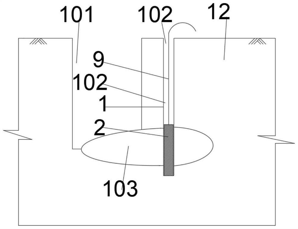
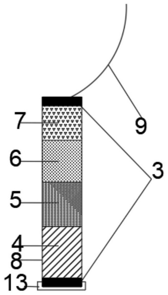
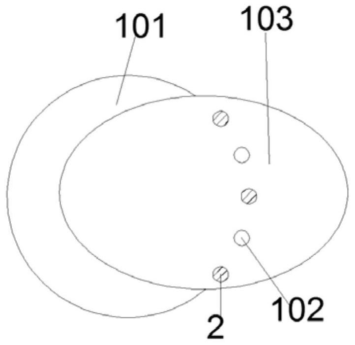
[0037] S1. Use a coring machine to drill the boulder 103 and set a borehole 102, wherein the borehole 102 is arranged 30-50 cm away from the edge of the pile hole 101, and the distance from each borehole 102 to the center of the pile hole 101 is equal; The distance between 102 is 20-30cm, an...


PUM


Abstract

The invention relates to a construction method of a complex inclined rock and boulder geological bored pile. The construction method comprises the following steps of: S1, drilling first drill holes ina foundation and boulders on the pile side by using a coring machine; S2, manufacturing an explosive tube; S3, burying wall protecting tubes in the first drill holes every other first drill hole; S4,mounting a lifting rope at the top of a limiting rod; S5, sleeving the outer side of the limiting rod with a steel casing to the highest point of the rock surface; S6, pre-cracking and loosening rocks by using a static crushing agent; S7, lifting the lifting rope to recover the limiting rod and a PVC tube for secondary utilization; S8, arranging a geotextile bag at the position, corresponding toa boulder hole, of a reinforcement cage; S9, arranging water-swellable rubber between a first iron sheet and a second iron sheet; and S10, sinking the assembled reinforcement cage to a designated position, and pouring concrete. The construction method has the advantages that the limiting rod is arranged on the inclined rock and boulders, so that the casing can be prevented from deflecting; and when a drill bit is ejected and deflects to affect the casing, the drill bit can be limited by the limiting rod, so that the perpendicularity of a pile hole is improved.

Description

technical field [0001] The invention relates to the construction of bored cast-in-place piles, in particular to a construction method of bored cast-in-place piles in complicated inclined rock and boulder geological conditions. Background technique [0002] When bored piles are constructed in areas containing granite in the stratum, boulders (spherical irregular weathering of granite) are often encountered, which makes it difficult to form holes for bored piles. Due to the high strength of the granite boulder, the bored pile cannot be constructed to the design height; when the drill bit of the bored pile encounters inclined rock, due to the deflection of the rock surface, the impact drill bit is easily deflected by ejection, resulting in Deviation, the existing technical scheme for rectifying the deflection is: throwing and filling high-strength flakes, and then using a percussion drill to impact and rectify the deflection; after measuring the inclination of the drilled hole ...

Claims


Application Information

Patent Timeline
Patent Type & Authority Applications(China)
IPC IPC(8): E21B7/00E21B25/00E02D5/38E02D17/08
CPCE02D5/38E02D17/08E02D2300/0006E02D2300/002E02D2300/0029E02D2300/0085E21B7/007E21B25/00
Inventor 王新泉崔允亮刁红国
Owner ZHEJIANG UNIV CITY COLLEGE
Why Eureka
Try Eureka